l Definitions, Purpose and Significance

Viscosity is one of the important indicators of coating products, and it is a reliable method to determine the molecular weight of polymers in paints. In the process of tree brain synthesis, it is particularly important to control the size of viscosity, if the viscosity grows too fast and too large, there will be a danger of gelatinization, on the contrary, the viscosity grows too slowly, which is time-consuming and energy-consuming. The viscosity also needs to be strictly controlled in the process of lacquering, and the slightest negligence of some paints will make the viscosity too large, and even gelatinize the paint, resulting in losses. When the viscosity is too low, the solvent that should be added will not be added, which will not only cause the cost to rise, but also cause a lot of quality problems, such as the adhesion Tester of the paint film and other physical and mechanical properties will deteriorate, the gloss will be reduced, and the weather resistance, water resistance, and chemical resistance of the paint film will be poor, so the determination of the viscosity of the paint is very necessary for the control of the coating production process and the quality of the final coating product. For the construction of sub-coatings, the viscosity of the paint is too high to make the construction difficult, the brush can not be pulled away, the nozzle is blocked when spraying, and the leveling of the paint film is poor 1.
2 Xiangmei standard
GB/T 1723-93 Coating viscosity determination method. GB/T 6753.4-1998 Determination of outflow time for color paints and varnishes with outFlow Cups
GB/T 2794-1995 Determination of adhesive viscosity
GB/T 9269-88 Determination of viscosity of architectural coatings - Stormer viscometer method
GB/T 9751-88 Determination of viscosity of coatings at high shear rates
3. Introduction to the key points of the inspection method
3.1 GB/1723-93 Coating Accuracy Determination Method
This standard specifies the method for determining the viscosity of coatings by using a coating 1L, coating 4 viscometers and falling ball viscometers.
3.1.1 Coating 1 viscometer method
3.1.1.1 Test Principle
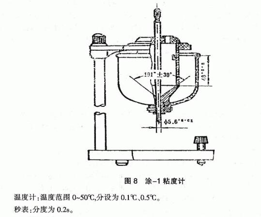
The viscosity measured by the Tu-1 viscometer is the conditional viscosity. It is the time for a certain amount of sample to flow out of a hole of a specified diameter at a certain temperature, expressed in seconds (s). This is used to determine paint products with an outflow time of not less than 20 seconds.
3.1.1.2 Instruments
The specifications and dimensions of the viscometer are detailed in Figure 8. The upper part of the viscometer is cylindrical, and the lower part is a conical metal container. There are graduation lines on the inner wall, because there is a leaky mouth at the bottom of the inlay. There are two holes in the lid of the container, one for the plug trap and the other for inserting a thermometer.
3.1.1.3 Operational Points
Before each measurement, the inside of the viscometer must be wiped with gauze dipped in solvent, dry in the air or dried with cold air, and the leaky nozzle of the viscometer should be cleared by observing the light, and then the viscometer should be placed in the Water Bath sleeve, supplemented with a plug rod, and the sample is stirred evenly, and when there are crusts and granules, filter with a metal sieve with a pore size of 246 μm, adjust the temperature to (23i1) °C or (25±1) °C, and then pour the sample into the viscometer, adjust the horizontal screw to make the liquid level coincide with the engraved line. Close the lid and insert the thermometer to maintain the temperature of the specimen (thermostatic sink). Place a 50 ml measuring cup under the leaky mouthpiece, and when the temperature of the sample meets the requirements, quickly lift the stopper rod, and start the stopwatch immediately when the sample flows out of the leaky mouthpiece. When the sample in the cup reaches the 50 ml scale line, the stopwatch is stopped immediately, and the time (seconds) required for the sample to flow into the cup for 50 ml is the conditional viscosity of the sample. The difference between the two measurements should not be greater than 3% of the average value, and the average value of the two measurements is taken as the measurement result.
3.1.2 Coating 4 viscometer method
3.1.2.1 Test Principle
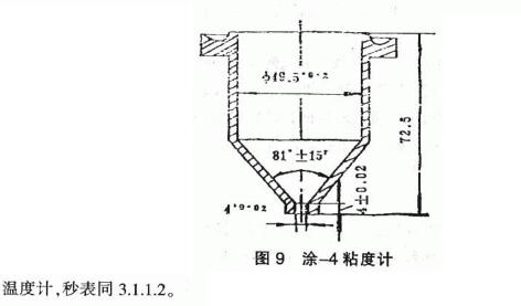
The viscosity determined by the coat_4 viscometer is also a conditional viscosity. The test principle is the same as that of the 1-viscometer method. It is suitable for measuring paint products with an outflow time of less than 150 seconds.
3.1.2.2 Instruments
The specifications and dimensions of the coating_4 viscometer are shown in Figure 9. It is a cylindrical metal container in the upper part and a conical shape in the lower part. The tapered bottom has a drain mouth. There is a ring of dimples in the upper part of the container, which is used as a spill of excess specimens. It is available in two materials: plastic and metal.
3.1.2.3 Operational points
The cleaning treatment of the viscometer and the preparation of the sample are the same as those described in the measurement method of the viscometer with a l, and the horizontal screw is adjusted to make the viscometer in a horizontal position. Place a 150 ml porcelain cup under the leaky mouth of the viscometer, plug the leak with your fingers, pour the (23i1)°C or (25·1)°C sample into the viscometer, and scrape the bubbles and excess samples with a glass rod or glass plate. Release your finger and start the stopwatch at the same time, stopping the stopwatch as soon as the flow of the specimen is interrupted. The time (seconds) for the specimen to flow out of the viscometer is the conditional viscosity of the specimen. The difference between the two measurements should not be greater than 3% of the average value, and the average value of the two measurements is taken as the measurement result.
3.1.3 Falling ball viscometer method
3.1.3.1 Test Principle
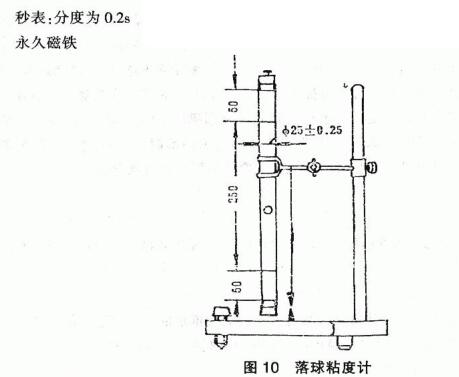
The viscosity determined by the falling ball viscometer is also the conditional viscosity. That is, at a certain temperature, the time required for a certain specification of steel ball to pass through the upper and lower two scale marks of the glass tube containing the sample. It is suitable for the determination of transparent liquid products with high viscosity.
3.1.3.2 Materials and instruments
The specifications and dimensions of the falling ball viscometer are shown in Figure 10. It consists of two parts: a glass tube and a steel ball. There are graduation lines at 50 meters from the edge of the nozzle at both ends of the glass tube, the distance between the two lines is 250 mm, there are cork stoppers on the nozzle and the lower end, and there is an iron nail in the middle of the cork at the upper end, and the glass tube is vertically fixed on the frame (measured by a plumb hammer). The diameter of the steel ball is (8±0.03) mm.
3.1.3.3 Operational Points
Pour the transparent sample into the tube, make the sample height mark 40mm, and put the steel ball into it together, plug the cork with iron, place it on the cork with iron nails with a long-term magnet, turn the tube upside down so that the iron nail sucks the steel ball, and then flip it over, and then take away the long-term magnet, so that the steel ball falls white, start the stopwatch immediately when the steel ball passes through the upper scale mark, stop the stopwatch when the steel ball falls to the lower scale line, and record the time (seconds) when the steel ball passes through the two scale lines, which is the conditional viscosity of the sample. The difference between the measured values of the strokes should not be greater than 3% of the average value, and the average value of the two measurements is taken as the measurement result.
3.1.4 Precautions
3.1.4.1 Coating 1 viscometer, coating 1 sticking new top must be J Shun horizontal, so as to ensure the vertical position of the leaky mouth, the finger should be released quickly and naturally during the measurement, do not shake the viscometer, and the operating environment should not have mechanical vibration and other disturbances.
3.1.4.2 The paint liquid should be transitioned according to the regulations, so as to avoid crust, impurities and large particles blocking the mouth of the tree and not being accurate.
3.1.4.3 The temperature needs to be strictly controlled to meet the requirements
3.1.4.4 After the measurement, the Viscosity Cup needs to be cleaned with an appropriate solvent, do not scrape with hard objects such as metal wires, if the lagoon has its own dry, new appendages, it should be soaked with an appropriate solvent and then cleaned with a soft fabric through the drain, wiped and preserved. Before using the viscometer, it is necessary to check whether the viscometer is clean, and the viscometer that has not been used for a long time should be cleaned and dried before storage.
3.2 GB/T 6753.4-1998 Determination of outflow time for base paints and varnishes with outFlow Cups
3.2.1 Test principle
The time elapsed at the moment when the chamber of the tested material begins to flow out from the filled outFlow Cup is close to the moment when the material flow beam at the outflow hole is initially interrupted, which is the outflow time of the tested material, expressed in seconds (s). This method is suitable for the determination of fluids with Newtonian flow: and is limited to the measurement of test materials that can accurately determine the break point of the liquid flow flowing from the outflow hole of the self-flowing cup. When the outflow is the same as the test material for more than 100s, due to the delay effect, the breakpoint is difficult to determine and the repeatability is poor.
3.2.2 Instruments and equipment
OutFlow Cup: For details of the size specifications, see GB/T 6753.4-1998. The tightest tolerance required is the outflow spout diameter, as the outflow time is inversely proportional to the fourth power of this inner diameter size.
Thermometer: accurate to 0.2°C, indexing interval of 0.2°C or finer.
Stopwatch or other timer: the index is 0.2 seconds or less, and the accuracy should be within 0.1% when the test time is less than 60 minutes.
3.2.3 Operational Points
3.2.3.1 Preliminary Testing
Select the outFlow Cup of a certain grade to be able to get 30s to 100s of the outflow of the tested sample. Release your finger within 5 seconds of the sample loading the outFlow Cup for measurement, and record the outflow time; Repeat the assay, but this time keep the specimen in the outFlow Cup for 60 seconds before releasing your finger. If the difference between the second and first results is greater than 10% of their average, the specimen is considered non-Newtonian and therefore not suitable for viscosity determination by this method. 3.2.3.2 Outflow time determination
Select the outFlow Cup of a certain grade so that it can get the outflow time between 20s and 100s for the sample under test, and it is recommended to be between 30s and 100s. Adjust the temperature of the sample, block the hole of the outFlow Cup with one finger, pour the sample into the cup, pull the glass plate horizontally through the edge of the outFlow Cup, make the horizontal plane of the sample and the upper edge of the outFlow Cup in the same horizontal position, measure, record the time, accurate to 0.5s. 3.2.4 Presentation of results
Repeat the test twice to calculate the average of the two assays. If the difference between the two measurements is greater than 5% of the average, a third measurement is performed. If the difference between the third measurement and the previous two measurements is not greater than 5% of the average value, the average value of the two acceptable measurements is calculated as the result after discarding the value exceeding the required value. If the second measurement still does not produce the required measured value, it is due to . The specimen has irregular fluidity and is not suitable for this method, and other test methods should be considered.
3.2.5 Precautions
3.2.5.l The outFlow Cup should be cleaned with a suitable solvent immediately after use and before the sample begins to become thousands. Metal cleaning tools or wires should never be used. If the outflow hole is dried sediment, the ancient stain 1 should be softened with the solvent of Tongxuan, and then carefully cleaned and resolved, for example, with a soft cloth through the outflow hole to wipe and clean.
3.2.5.2 During the test, the thermometer can be inserted into the sample flow, but it should not interfere with the observation of the flow interruption. The temperature difference of the regulation should not be greater than 0.5°C.
3.3 GB/T 2794-1995 Determination of adhesive viscosity
3.3.1 Test Principle
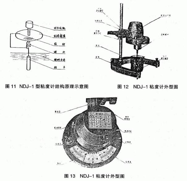
Generally, high-viscosity liquids and viscous paints and latex paints all have non-Newtonian fluidity, and the viscosity of non-Newtonian liquids, i.e., the ratio of shear stress to shear rate, is a variable that varies with the shear rate. Cylinders, discs or slurry blades are usually rotated in the paint specimen to produce a gyratory flow, and the stress required to reach a fixed shear rate is measured, which is converted into viscosity.
3.3.2 Instruments and equipment
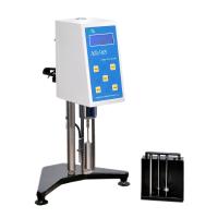
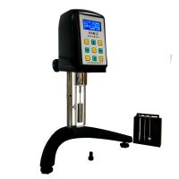
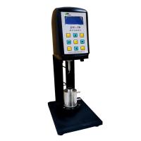
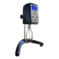
Rotational viscometers have developed rapidly with the research of rheology, and there are many types of viscometers. From the shape of the rotating parts, there was a concentric garden simple type earlier, the inner (outside) simple rotation, the outer (inner) cylinder fixed, and the sample was sheared between the inner and outer cylinders, and later developed to the pulp garden disc type and cone plate type. Fig. 11, Fig. 12 and Fig. 13 are schematic diagrams of the structural principle and appearance of NDJ= 1 type Rotational Viscometer.
Thermometer: 0.1°C index.
3.3.3 Operational Points
Depending on the viscosity of the sample, select the appropriate rotor and rotation speed to make the reading within the range of 20-80% of the dial, balance the sample temperature with the test temperature, and keep the sample temperature uniform. The rotor is vertically immersed in the center of the sample, and the liquid level reaches the rotor level marking, and the rotation accuracy meter is activated. Reads the reading when the pointer is unchanged on the disc when it is rotated.
3.3.4 Presentation of Results
Each specimen is measured three times, and the smallest value of the three specimen tests is taken as the test result, and three significant figures are taken.
3.3.5 Precautions
3.3.5.1 When loading and unloading the rotor, you should be careful not to use too much force to avoid bending the rotor. After the rotor is installed, it is not allowed to put the instrument sideways or backwards.
3.3.5.2 The end face and thread of the connecting screw and rotor should be kept clean, and the rotor should be cleaned in time after each use, and properly placed in the sub-rotor frame.
3.4 GB/T 9269-88 Determination of viscosity of architectural coatings - Stormer viscometer method
3.4.1 Test Principle
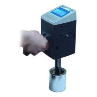
The load required to produce a 200 r/min speed is tested using a Stormer viscometer and the viscosity of the coating is expressed as either that load in grams or a logarithmic function of that load in Krebs units (KU).
3.4.2 Instruments and equipment
Fig. 14 is the appearance of the REF·407 rotary industrial viscometer, which is a Stormer viscometer with a strobe timer. The REF, Model 4or7 rotary industrial viscometer determines the viscosity of non-Newtonian liquids, including most coatings, by controlling the rotational speed of the rotating paddle with a strobe observer, mechanically operated by load.
Thermometer: The measuring range is 0~50°C, and the index is 0.1°C.
Stopwatch: 0.2s in divisions.
3.4.3 Operational Points 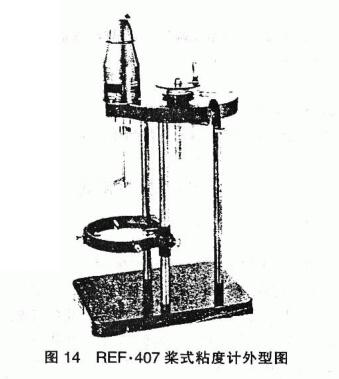
Stir the paint well and move it into the container, keep the temperature of the paint and viscometer at (23±0.2) °C, and immerse the rotor in the paint so that the paint liquid level just reaches the mark of the rotor shaft. The tests were carried out according to method A (no strobe timer) and method B (frequency timer). Repeat the measurement until a consistent loading value is obtained.
3.4.4 Presentation of Results
The results of the test are expressed in grams or Ku values. In method A, according to the number of grams of special codes required to produce 100lr/30s, the Ku value is obtained from the corresponding table of load and Ku value. In method B, according to the number of grams of special codes necessary to generate 200/㎟n or 100r/30s graphics obtained from the test, the Ku value is obtained from the corresponding table of load and Ku value.
3.5 GB/T 9751-88 Determination of viscosity of coatings at high shear rates
3.5.1 Test Principle
Same as 3.3.1, the standard stipulates that the dynamic viscosity of the coating is determined at the shear rate of 5000~20000s', and its purpose is to determine the viscosity of the coating under the high shear-shear rate during the construction process.
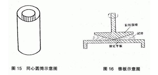
3.5.2 Instruments and equipment
Concentric cylindrical viscometers (see Fig. 15) and conical plate viscometers (Fig. 16) are the two commonly used viscometers.
.5.3 Operational Points
Adjust the temperature of the national part of the viscometer (stator or plate) to an appropriate temperature, take an appropriate amount of tested product to the appropriate part of the viscometer, start the rotor, and when the pointer reaches stability, write down the reading.
3.5.4 Presentation of Results
The results are executed by Pa· s indicates that if the instrument reading does not directly represent the viscosity, the viscosity is obtained by applying the appropriate conversion factor or using this correction curve. Parallel assays are performed twice; The relative error between the two measurement results should not be greater than 5%.