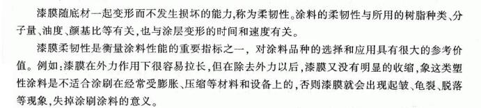
1 Definitions, Purpose and Significance
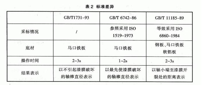
2 Relevant Standards
GB/T 1731-93 Determination of initial flexibility of paint film
GB/T 6742_86 Rattan membrane flexure test (Guogui axis)
GB/T11185_89 Paint Film Bending Test (i-Shaped Shaft)
GB/T1748-79 (89) Determination of Initial Flexibility of Putty Film
ISO 1519:2002 Bending Test for Paints and Varnishes
3. Introduction to the key points of the test method
3.1 GB/T1731-93 Paint film flexibility determination method
3.1.1 Test Principle
By deforming the paint film and the substrate together, the elongation of the paint film is detected, including the interface between the paint film and the substrateFunction.
3.1,2 Materials and Equipment
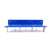
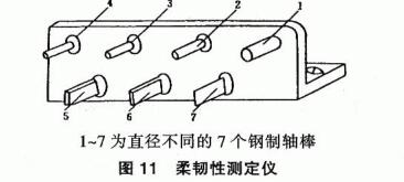
The Flexibility Tester QTX Paint Film Elasticity Tester is shown in Figure 11 and consists of 6 copper shaft rods with different groups, each
The length of the shaft rod is 35mm, and the radius of curvature is 0.5mm, 1mm, 1.5mm, 2mm, 2.5mm, 5mm, and 7.5mm.
Tinplate: 1.20mmx25mmx(0.2~0.3)mm
3.l.3 Operational Points
With the paint film side facing up, press the painted sample tightly on the shaft rod of the required diameter with both hands, bend it around the rod within (2-3)s, and after bending, the two thumbs should be symmetrical to the center line of the shaft rod.
3.1.4 Determination of Results
Use visual inspection or a 4x magnifying glass to observe whether the paint film has damage phenomena such as mesh, cracks and peeling, and the flexibility of the paint film is indicated by the minimum shaft rod diameter of the sample bent on the shaft rod of different diameters without causing the damage of the paint film.
3.1.5 Precautions
3.1.5,1 The model should be pressed tightly against the shaft rod.
3.1.5.2 The bending action should be completed within (2~3)s.
3.1.5.3 The force of both thumbs should be even when bending.
3.2 GB/T6742-86 Paint film bending test (cylindrical shaft)
3.2.1 Test principle
Same as 3.1.1.
3.2.2 Materials and Equipment
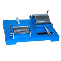
Cylindrical bender: as shown in Figure 12, it is suitable for test plates with a thickness of less than 0.3mm, and the diameter of the shaft rod is 2mm, 3mm,
、8mm、10mm、12mm、16mm、20rnm、25mm、32mm。
Tinplate: 120mmx50mmx(0.2-0.3)mm
3.2.3 Operational Points
Insert the sample into the instrument with the painted side facing the seat. Close the instrument smoothly and abruptly within (1-2)s, turn the sample 180° on the axis, bend it, and do not take out the sample.
3,2.4 Result Presentation
Use a visual inspection or a 10x magnifying glass to see if the paint film is cracked or peeled off the bottom plate (excluding coatings with a high edge of less than 1 () mm). Record the shaft diameter that preferentially cracks or strips the coating well. If the shaft with the smallest diameter does not break the coating film, it is recorded that the coating film does not break when bent on the shaft with the smallest diameter: 1 No.
3.2.5 Precautions
3.2.5.1 The substrate should be flat, free of twists, and free of visible wrinkles or cracks.
3.2.5.2 If the board is made by brushing, the direction of brushing should be parallel to the long side of the board.
3.2.5.3 The bending action should be completed within (1~2)s.
3.2.5.4 Improper operation should be avoided to cause the temperature of the sample to rise.
3.3 GB/11185-89 Paint film bending test (tapered shaft)
3, 3.1 Test principle
Same as 3, 1.1.
3.3.2 Materials and Equipment
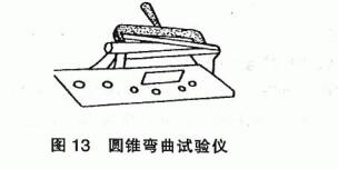
[L set L cone: bending Tester: as shown in Figure 13, the central axis is a circular body, and the diameter of the small end is 3.2mn; Diameter of the large end: 38mm; The length of the entire forging body is 203mm.
Steel plate, tinplate plate into several aluminum plates: 180mmx100mm, maximum thickness 0.8nm.
3.3.3 Operational Points
At a distance of 20mm from the short side of the test plate, cut the test board through in parallel, and trace the paint film side of the test board towards the tie rod, so that one of the short sides of the test board is in contact with the small end of the shaft. After the test plate is held in the center, bend the test plate evenly and smoothly with a tie rod so that it winds the axis 180° within (2-3)s. Record the crack of the test plate farthest from the small end of the spindle and remove the plate.
3.3.4 Presentation of Results
Use a visual or 10x magnifying glass to observe the opening or peeling off of the paint film from the test plate, and measure the distance from the small end of the shaft to the crack along the test plate, measured in cm. Measured three times, the average value was taken, and the results were accurate to the centimeter.
3.3.5 Precautions
3.3.5.1 The substrate should be flat, without twisting, and without visible wrinkles or lines.
3.3.5.2 The bending action should be completed within (2-3)s.
3.3.5.3 Improper operation should be avoided to cause the temperature of the sample to rise.
3.4 GB/T1748-79(89) Putty film flexibility determination method
3,4.1 Test Principle
Same as 3.1.1.
3.4.2 Materials and equipment
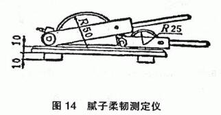
Crotch flexibility Tester: As shown in Figure 14, the instrument is composed of two semi-national arcs, with diameters of 50mm and 100mm respectively.
Tinplate: 155mmx85mmx(0.2-0.3)mm
3.4.3 Operational Points
The prepared putty film sample is polished to a thickness of 0.4mm with 320-500 water sandpaper, placed for 1h, and then fixed at one end of the instrument, and it is tightly attached to the surface of the round injection of the instrument with a rolling slip.
3.4.4 Presentation of Results
Observe whether the surface of the putty film is opened, and if not, the flexibility of the putty film is indicated by the diameter of the curved cylinder.
3.4.5 Precautions
3.4.5.1 The substrate should be coated with an iron red primer and flattened.
3.5 IS01519:2002 Pigment and varnish - bending test (cylindrical axis)
3.5.1 Test Principle
Same as 3.1.1.
3.5.2 Materials and Equipment
Type Tester: the same as 3.2.2 in the cylindrical bender, see Figure 12.
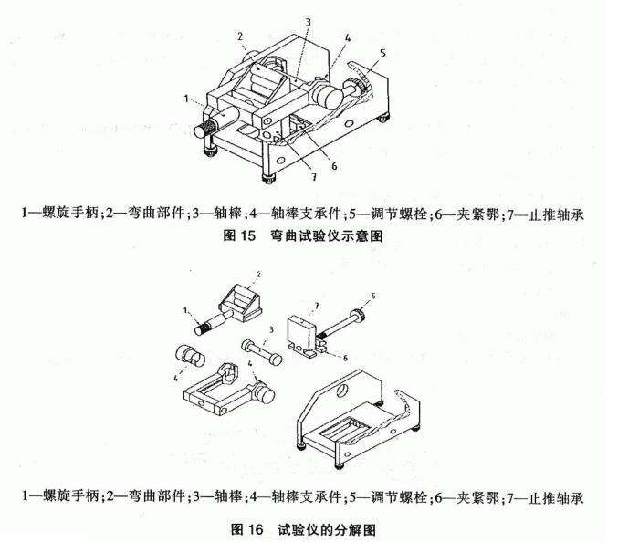
Type 2 Tester: As shown in Figures 15 and 16. It can be used for test boards with a thickness of up to 1.0mm. The shaft diameters are 2mm, 3mm, 4mm, 5nm, 6mm, 8mm, 1()mm, 12mm, 16mn, 20mm, 25mm, and 32nm.
Substrate, steel plate, tinplate plate, soft pin plate, plastic substrate can be used. For the type 1 Tester, the thickness of the test plate should not be large 0_3mm, and for the type 2 Tester, the thickness of the test plate should not be more than 1.0mm. If plastic sheets are used, the thickness can be up to 4 0.
3.5.3 Operational Points
3.5.3.1 Determine the steps with a specified single diameter shaft
(1) Test with a type 1 Tester
Open the instrument completely, attach the shaft rods, insert the template, and place the painted side facing the seat. Close the instrument at a steady speed rather than abruptly within 1s~2s to bend the test plate 180° around the axis.
(2) Test with type 2 Tester
Stabilize the instrument, insert the test plate from the top between the bending part and the shaft rod and between the thrust shaft and the central jaw, so that the coating to be tested is facing the axis rod with its back. Pull the adjusting bolt to move the thrust bearing so that the test plate is in a vertical position and in contact with the shaft. The plate is fixed with a clamping collar by rotating the adjustment media bolt. Turn the screw handle so that the bent part is in contact with the coating. The actual bending process is to lift the screw handle at a constant speed within 1s-2s to turn it 180°, so that the test plate is also bent 180°.
Turn the bolt handle to the initial position and remove the I-plate. Then loosen the bending parts and the central tightening collar with the appropriate operating parts (screw handle, adjustment bolts).
3.5.3.2 Procedure for determining the maximum pumping diameter that causes the failure of the normal layer
The test is carried out on a series of test plates according to the prescribed steps, and each test plate is inspected by the prescribed method, and the test is carried out with the shaft in turn until the coating cracks or peels off from the substrate. Find the shaft with the largest diameter that will cause the coating to crack or peel, repeat this step on another plate to be measured with the same shaft, and record the diameter after confirming the result. If there is no damage with the smallest diameter of the shaft coating, then the most coating on the smallest diameter of the shaft is recorded as electrical · There is no damage when the song is made.
3.5.4 Presentation of Results
In the case of a Type 1 Tester, the plate cannot be removed from the instrument during inspection. With normal vision or a 10x magnifying glass, check whether the coating is cracked or peeled off the substrate, and the coating within 10mm from the edge of the test board is not considered. If the result is expressed in a single output, the specified diameter of the shaft is used and the test plate is inspected to report whether the coating is cracked and/or neat from the substrate. If the result is expressed in terms of the maximum shaft diameter that caused the failure of the normal layer, the maximum shaft diameter that cracks the coating by 1f and/or spalls from the substrate is reported, or the shaft with the smallest diameter is reported to have no failure.
3.6 Factors influencing the test results
3.6.1 Influence of the degree of substrate grinding: the more uniform and effective the substrate grinding, the better the flexibility.
3.6.2 Temperature influence: the higher the temperature, the softer the paint film, and the better the initial flexibility.
3.6.3 Thickness effect: the thinner the paint film, the better the flexibility.
In addition, when bending the sample, the movement, speed, time, etc. of the hands will have different degrees of influence on the flexibility of the paint film. 4 Comparison between methods
These five methods of the paint film flexibility determination method are similar in terms of test principle, but they have their own advantages and disadvantages. GB/T 1731_93 It is convenient and is used by most domestic manufacturers. GB/T 6742_86 "Paint Film Bending Test (Cylindrical Shaft)" and IS01519:2002 "Paint and Varnish Bending Test" belong to the same method, GB/T 6742-86 is based on the standard of IS0 1519 1973, both methods are the use of the whole plate test, and the palm does not directly contact the paint film, eliminating the influence of the human body on the temperature increase of the test plate. GB/T 1 1 185-89 "Bending test of paint film (conical axis)" also uses a whole plate test and avoids the discontinuity of results caused by a set of conventional shaft holders. GB/T 1748-79(89) "Determination of Initial Flexibility of Putty Film" is specially used for the determination of initial flexibility of putty film, which is highly targeted, simple and convenient to operate. In addition, there are differences in the inspection process for the three standards GB/TL731-93 "Paint Film Flexibility Determination Method", GB/T 6742_86 "Paint Film Bending Test (Cylindrical Axis)" and GB/T 11185_89 "Paint Film Bending Test (Machine Axis)", as shown in Table 2: