Coating surface roughness refers to the micro-geometric characteristics of the coating surface with small spacing and microscopic peak-to-valley roughness.
The surface roughness of the coating not only directly affects the appearance quality of the coating, but also indirectly affects the corrosion resistance and service life of the coating, and even the strength and wear resistance of the coated product, as well as the precision of the workpiece, power consumption and noise, etc. wait. Therefore, when inspecting the appearance of coatings, not only decorative coatings and protective-decorative coatings need to be inspected, but also some functional coatings such as wear-resistant coatings and anti-friction coatings should be inspected for surface roughness.
As far as the appearance quality of the coating is concerned, both roughness and brightness can be directly reflected, that is, the lower the roughness of the coating, the higher the brightness, and the better the appearance quality of the coating. (Related instrument: Gloss Meter) However, no matter from the nature of Westerners or the evaluation methods and standards, they are not the same. Some coatings have good brightness but not low roughness, while some coatings have good gloss. The brightness is poor, but its roughness is low (i.e., the luminosity is high). Therefore, the roughness and brightness indicators of the coating should not be confused and should be strictly distinguished.
Test method for surface roughness
Surface roughness measurement belongs to microscopic length measurement, and the methods used recently include comparison method, optical method, needle drawing method and impression method. In the coating roughness test, the comparison method (sample control method), needle drawing method (contact method) and light section method are commonly used. (Related instrument: roughness measuring instrument)
In order to correctly reflect the actual roughness of the surface of the coating, the following items should be paid attention to during the inspection:
(1) The surface roughness value in the measuring direction is measured on the normal section (processing knife line) perpendicular to the measured surface, so the measuring direction is different, the height and distance of the small peaks and valleys on the surface are different, and the measured roughness The values are also different, as shown in Figure 11_1_7.
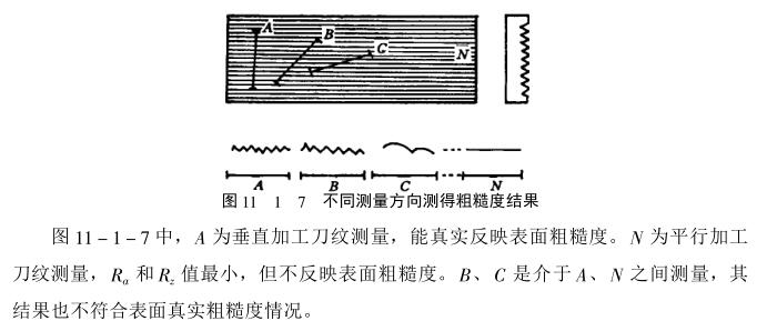
For this reason, when inspecting the surface roughness of the coating, it should be carried out strictly in the measurement direction specified in the technical documents. If the document is not specified, it should be measured in the direction that can obtain the maximum value of Ra or Rz.
(2) Measurement location Since the roughness values of different parts of the coating are not exactly the same, when measuring the surface roughness, one or several representative locations on the main surface of the coating should be selected for measurement. Then, the roughness of the coating is comprehensively evaluated according to the measurement results of each place.
(3) Surface defects such as; pinholes, pits, burrs, etc. are not included in the roughness value, and cannot be used as a standard for evaluating whether the roughness is qualified.
(4) The basic length and measuring length shall be carried out according to technical regulations, so as to prevent the influence of shape errors and waviness on the measurement results.
Commonly used coating surface roughness inspection methods are as follows:
1) Sample control method
The sample control method belongs to the daily measurement method in the comparison method. In the inspection, the standard roughness sample is used to compare with the inspected coating, and the texture, reflective intensity and color of the processed surface are repeatedly observed. Finally, when the inspected coating is close to a certain standard sample, the roughness of the sample is determined. The roughness value is used as the roughness of the tested coating.
The sample control method cannot measure the specific value of the coating roughness, but can only qualitatively evaluate which level the coating roughness belongs to. Because the method is simple and easy to implement, it is generally used when the measurement requirements are not very strict. It should be pointed out that The most important thing is that the standard roughness sample is a standard measuring tool, which needs to be produced by a professional factory and can only be used after strict testing and calibration.
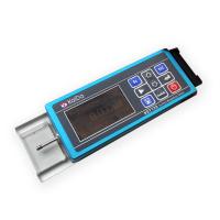
2) Profiler measurement method
The profilometer measurement method belongs to the needle drawing method (also known as the contact angle measurement method), and its types include mechanical, photoelectric and electric. Because the electric profilometer has small size, light weight, high magnification, rapid measurement and energy It has the advantages of directly displaying the Ra value by numbers, so it is widely used. Commonly used electric profilers include Taylor Schiff_4 (TALysuRF_4) (made in Britain), and "2201" and "GcN_2" (made in CHINA). The following introduces the measurement method of the "GcN_2" type electric profiler. The electric profiler is mainly composed of a measuring sensor composed of a diamond tip and a lead zirconium titanate piezoelectric body, a driver, a sample tube amplifier and its accessories. Its working principle is that when the actuator makes the diamond tip of the measuring sensor move a certain distance on the surface of the coating under test, the diamond tip moves up and down along the peak and trough of the coating surface under test to generate a certain amount of vibration. The magnitude of the quantity is converted into weak electric energy through the piezoelectric body, and then amplified and rectified by the body tube amplifier, and the corresponding characteristic parameter (Ra) value of the surface roughness of the measured coating is directly displayed on the meter. The indicated value of Ra is the roughness of the coating to be tested. The measuring range of the instrument is: Ra is between o.o2~5.00. When measuring, the "range switch" should be adjusted to the corresponding The position,, check method is as follows:
① Before using the instrument, check and adjust according to the instruction manual, and make calibration
② Wipe the surface of the coating to be tested, and check whether there are any abnormal defects on the surface, so as not to damage the diamond tip.
③Place the coated piece to be tested on the workbench as required, and make the diamond tip of the measuring head contact the corner parallel to the surface of the coating to be tested.
④Press the "Measurement" button, after the pointer is fixed on a certain position of the meter, read the Ra value on the meter, repeat the operation 2~3 times, when the error of the Ra value is not large, record the measured Ra value, ,
⑤According to the measured value of Ra, the surface roughness of the tested coating can be obtained, and the matters needing attention are as follows:
① When replacing the measuring head, it is necessary to calibrate the benchmark indication value of the instrument according to the requirements again,
② For continuous measurement, calibration and checking should be carried out at regular intervals.
③ If necessary, measure the surface roughness of 2~3 parts on the surface of the tested coating, and then calculate the average value of several roughness characterization parameters Ra.
3) Non-contact angle-out inspection of coating roughness
Non-contact angle-out measurement of coating surface roughness, commonly used optical section method to enlarge the image of surface microscopic unevenness, or use interferometry to show it as the curvature of the interference band, and then measure it, so the basic method is as follows: There are two kinds of optical section method and interferometry method. The light section method is based on the light section principle to measure the surface roughness. Interferometry is the use of the principle of light wave interference to measure surface roughness.
4) Roughness inspection by impression method
The impression method is a non-contact angle-out method for quantitatively measuring surface roughness. For some large and bulky parts and internal surfaces that are difficult to measure directly (such as holes, grooves, etc.), it is inconvenient to use instruments to measure the roughness, and the impression method is generally used for measurement. It is also sometimes measured with additionally designed auxiliary devices or special measuring instruments in the measuring instrument.
The principle of the impression method is to use some block-shaped plastic material as an impression, stick it on the surface of the part to be tested, print the outline of the surface to be tested on the bonding surface after it is removed, and then test the impression Measured to get the parameter value of rental roughness. Since the strength and hardness of the impression material are not high, it cannot be measured by the angle-out method. Because the impression material cannot fully reach the bottom of the micro-roughness of the measured surface, the measured roughness value of the impression is always smaller than the actual value of the actual contour of the measured surface. For this reason, the surface roughness measurement results obtained from the impression need to be corrected.