Viscosity is the main physicochemical property of liquid and colloidal systems. Judging from the point of use after construction, the viscosity can also indicate the quality of the paint material.
The determination of viscosity (viscometry) is of great significance in elucidating the structure and properties of polymer compounds. Viscometry is a reliable method for determining the molecular weight of polymers, because it has been proved by experiments that there is a proportional relationship between the viscosity and chain length of polymers.
The ability of a liquid to resist the motion of its molecules under the influence of an applied force is called viscosity or internal friction.
Viscosity can be divided into: dynamic viscosity, kinematic viscosity and relative viscosity. Dynamic viscosity and kinematic viscosity are absolute viscosities, both expressed in CGS units.
Determination of Viscosity with a Capillary Viscometer
Determination of dynamic viscosity
An instrument for the determination of dynamic viscosity. As shown in II of Figure 41. Its main part is the capillary viscometer. Each instrument is generally equipped with a set of five or six viscometers with capillary tubes of different diameters.
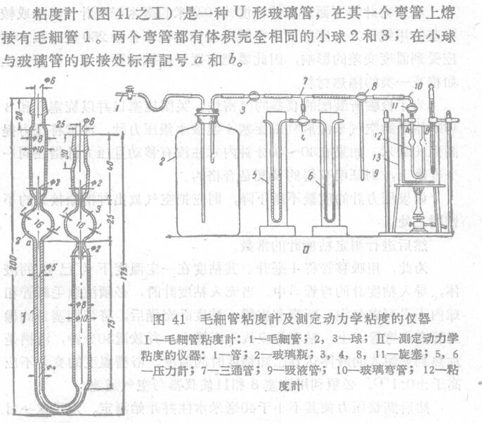
The most important part of the viscometer is the capillary. The inner diameter of the tube shall be the same throughout the length of the tube; capillary fittings with wide tubes shall be fitted as shown in the accompanying drawings. The viscometer is placed in a Water Bath (the diameter of the cup is not less than 100mm, and the height is not less than 200mm).
For viscosity determination at room temperature and at 100°C, water heated by a burner is poured into the bath. Put a calibrated thermometer with a graduation of 0.1° into the Water Tank. (Related instruments: constant temperature Water Tank)
The tail end of the elbow A is connected by a cock 11 and a glass elbow 10 with a three-way cock 8 connected to air by a suction pipe 9 . The glass bottle 2 has a volume of about 30 liters; this bottle acts as an "air buffer"; it communicates with the pressure source 1 and the three-way cock 3. Pressure gauge 5 (and 6 ) is a slightly wider u-shaped tube at its bend. The tubes are mounted on wooden bases with pin hammers and set screws. The inner diameter of the pressure gauge tube is not less than 3mm and not more than 4mm., and its outer diameter is not less than 5mm and not more than 6mm. One pressure gauge shall be filled with distilled water, and the other shall be filled with distilled tribute that has been cleaned with 10% nitric acid solution.
A millimeter scale (paper or better, mirror) with a graduation of 10 mm is placed under the manometer tube. The degree should be divided into 250 degrees from the middle zero degree up and down. Bottle 2 should not be affected by temperature variations, so it is placed in a labeled basket, well and covered with an insulating material such as cotton.
In order to check the airtightness of the assembled instrument, close the cock 11 well, cut off the air source of the system with cock 3 and 8, do not connect the mercury manometer with cock 4, and pay attention to increase the pressure to 20 mm. If the potassium inner agent does not move and the pressure gauge points to the same degree after 30-40 minutes, it proves that the assembly of the instrument is qualified. ·
If the degree of the pressure gauge keeps dropping, the air should be released from the well to eliminate the leaky joint . Then proceed to measure the number of viscometers.
For this purpose, use a pipette to introduce 4 ml of a liquid test tube A of the viscometer. When filling the viscometer, care must be taken that no air bubbles, breakage and film. After the viscometer is full, put the rubber tube with the cock 11 on the elbow A. The viscometer should be placed in the bath well and left for 30 minutes. The bath is heated to the temperature at which the poured liquid reaches a known viscosity. The bath temperature should not vary by more than ±0.1°C. It is necessary to utilize stopcock 8 and to vent the instrument to air.
Then adjust the pressure so that it is not less than 40 mm water column well to start the measurement. For this purpose , the cock 11 must be closed, while the system is isolated from the air by the cock 8 and connected to the pipe 10 . The instrument shall be kept in the new position until the moment when constant pressure is reached, and the time shall be recorded . Afterwards, flick the cock with one hand, and start the stopwatch with the other (when the liquid level in test tube 3 reaches mark a). Stop the stopwatch just as the liquid is reaching mark i. Plug 1 1 should be closed. Otherwise the pressure will drive the liquid out of elbow B. Write down the time on the stopwatch, and write down the reading on the pressure gauge again. -
Repeat determinations are then started. Turning the cock 8 isolates the viscometer from the pressure gauge and the pressure source, and allows the atmosphere to enter the instrument. Next, carefully suck the liquid below the mark a in the elbow B into the capillary well through the tube 9 and close the cock 11. Thereafter, increase the pressure well and repeat the test.
The meter must be carefully cleaned and dried before each use.
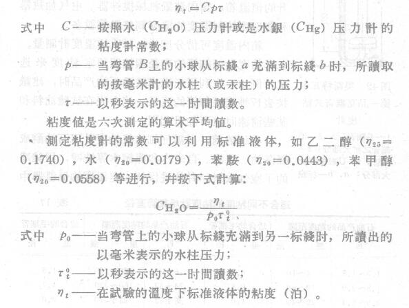
The dynamic viscosity η can be calculated according to the following formula when the measuring temperature is t:
Determination of Kinematic Viscosity
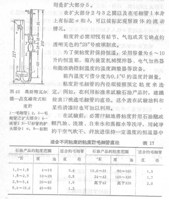
The Ostwald viscometer is recognized as a standard viscosity meter for determining the kinetic viscosity of petroleum products after being improved by Pinkovich.
The viscometer shown in Figure 42 is a u-shaped glass tube with a capillary 1 welded on one of its bends and connected with capillary blown enlarged parts 2 and 3. The upper part of the bent pipe has a small branch pipe 4, which is used to connect the rubber tube when drawing the test solution, while the lower part of the bent pipe is an enlarged part.