Temnikov proposed an electric rotor viscometer that operates on the principle that a body rotates in a liquid.
The operating principle of the viscometer lies in the change of the dynamic resistance of the motor when the cap hole of the motor is not in the test liquid. When the viscosity of the liquid changes, the torque of the liquid to the rotation speed also changes. This rotation The speed is proportional to the viscosity under the condition that the rotational angular speed does not exceed a certain critical value. The schematic diagram and schematic diagram of the electric rotor viscometer are shown in Figure 47.
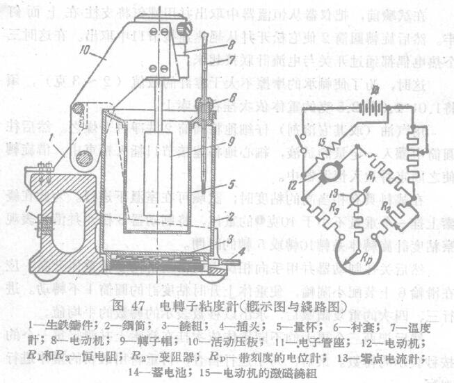
The pedestal of the instrument is a cast iron component 1, and the bottom is equipped with a steel cylinder with a heating group 3. The heating winding is terminated with three heaters for supplying alternating current: the contact head 4, and a test solution filled with The detachable measuring cup 5 is used to fix the thermometer 7 in the thermostat with the bushing 6, and the motor 8 with the sub-panel 9 is fixed on the upper part of the movable platen 10 when it rotates 90°. The platen 10 can be moved from the measuring cup to the body Pull out the sub, then remove the rotor from the shaft. (Related instruments: constant temperature and humidity Test Chamber)
The wires are led to the electronic tube base 11 fixed on the base of the instrument, and all the mechanical management is concentrated on the operating table connected with the electric motor by means of the electric group, and the zero-point ammeter and the The dial of the potentiometer, the degree of the viscosity unit engraved on the top of the dial of the potentiometer; the viscosity of the test solution can be directly set on the dial.
The circuit state of this instrument is similar to that of Esden electric mining circuit diagram.
The armature of the shunt motor 12 is connected to a bridge tube, and the other bridge tubes are composed of value resistors R1 and R3, a rheostat R2, and a potentiometer Kp with a dial, and a zero-point ammeter with a supplementary resistor 13 In one diagonal group of the electric bridge, a 12-volt storage battery is connected on the other diagonal. , When the motor is idling (rotating in the air), it is adjusted at zero degrees. Other electric (synchronous) rotor viscometers of the Gorky Institute of Physics and Engineering have also attracted great interest.