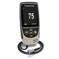
PosiTector 6000 Coating Thickness Gauge Instructions for Use Version 6.0 is available for both Basic (1) and Standard (2),Posifector6000Handheld electronic Thickness Gauges provide fast, accurate, and non-destructive metal thickness measurements.
How it works:
The F probe uses a magnetic method to measure non-magnetic coatings on ferrous metalsThickness.
The N probe uses the eddy current method to measure non-conductivity on non-ferrous metalsCoating thickness.
The FN probe combines all the features of the "F" and "N" probes.
Note: In this manual, the W symbol indicates that more information about the topic or feature is available on our website.
certificate
allPosifector6000The probe or Thickness Gauge comes with a calibration certificate. For organizations that need to recertify, the gauge can be sent back for calibration on a regular basis, DeFelsko recommends that customers determine the calibration interval of the gauge based on their own experience and working environment, based on our product knowledge, data and customer feedback, usually based on the one-year calibration cycle starting on the calibration date, purchase date or receipt date.
Power on/off
The PosiTector 6000 can be turned on at the press of any button, and to extend battery life, the gauge will automatically shut down if there is no operation for 3 minutes. All settings remain the same.
Get started quickly
1. Please remove the black protective rubber cover (if any) from the probe for the split probe one, and take out the Thickness Gauge from the rubber protective cover for the built-in probe one.
2. Press any button to turn on the Thickness Gauge.
3. Place the probe close to the surface being measured. Hold this position and when a valid measurement is completed, the gauge will beep twice and the two-color indicator will flash green and display the measurement data.
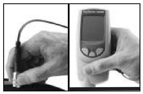
4. Move the probe at least 2 inches (5 cm) away from the surface being measured between adjacent measurements, or take continuous measurements at the same location on the surface being measured every 2 seconds, and do not drag the probe along the surface to one side.
criterion
Measure the uncoated part first! This quick zero-check operation determines if calibration adjustments are needed for the matrix. (See page 5)
The included calibration foil is then placed on an uncoated substrate and measured separately to ensure that the known thickness measured by the gauge is within tolerance.
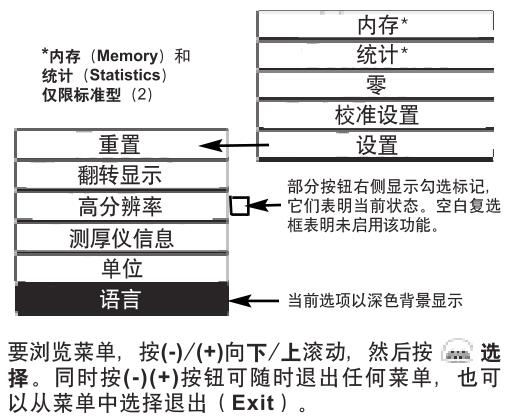
Menu actions
Control the Thickness Gauge function via the menu, to access the menu, open the Thickness Gauge, W and press the button.
Calibration, verification, and adjustment
These 3 steps ensure high accuracy
1. Calibration is usually done by the manufacturer or a laboratory with appropriate qualifications
2. Accuracy verification is completed by the user
3. Adjust one to a known thickness
calibration
Calibration is a controlled, evidence-proof process that measures and tracks calibration standards and verifies that results are presentPosifector6000Within the nominal accuracy of a Thickness Gauge, calibration is typically made by the gauge manufacturer or a suitably qualified calibration laboratory in accordance with a process prepared with proof in a controlled environment. W
verify
Verification is an accuracy check performed by the user against a known reference standard, and for the verification to be successful, the data read by the gauge needs to be within the combined accuracy of the gauge and the reference standard.
adjust
Adjustment or calibration adjustment is the operation of aligning the thickness reading data of a Thickness Gauge with the data of a known thickness sample, which is designed to improve the effectiveness of the Thickness Gauge in a specific surface or an area of the measurement range. Single-point or 2-point calibration adjustments can be taken and they will be stored in the calibration settings (page 9)
Note: After each calibration adjustment of the gauge,  The symbol disappears.
The PosiTector 6000 is calibrated at the factory and performs an automatic self-test every time it takes a measurement, and in most cases, no additional adjustments are required after the reset (page 11). Simply check if the uncoated substrate is zero (ZER〇) and then measure.
However, the data reading of the gauge may be affected due to the matrix shape, composition, and surface roughness, or different areas of the measurement section, so a calibration adjustment function is provided. If the reading data is outside the desired range of the thickness of the analyte, a single or 2-point calibration adjustment can be made.
If no calibration adjustment method is specified, use the single-point method first, or the 2-point method if the supplied calibration foil cannot be accurately measured. Factory calibration settings can be restored at any time by resetting (page 11) and the screen will be displayed each time the factory calibration settings are used Symbol.
Note: For "FN" Thickness Gauges, calibration adjustments can only be made in "F" or "~N" mode (stored separately in a specific calibration) and the last calibration adjustment is used.
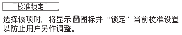
Note: Once you have finished adjusting, you can "lock" the current calibration adjustment to prevent this setting from being altered. (See "Cal Lock" on page 9)
Single-point calibration adjustment
Also known as an offset or correction value, there are 4 ways to make this adjustment:
(1) Simple zero calibration adjustment
Measure the part without the remainder. If the gauge does not display "0" within the tolerance of the transducer being used, move the transducer away from the surface and adjust the display down (-) or up (+) until the screen shows "0".
(2) Average zero calibration adjustment
To read "0" on a rough or curved surface, the first way to consider is to read the thickness of the uncoated part several times and calculate the average of the results.
1. Select the Zero menu option, 2. Press (+) to select the number of reads to be used to calculate the average (usually 3-10 reads), the greater the difference in the read data, the number of reads should be increased to calculate the average.
3. Repeat the thickness of the uncoated part. The gauge waits 2 seconds between adjacent reads to allow the user to correctly place the transducer on the surface being measured, and after the last measurement, the gauge calculates the read data and displays a "0", which represents the average of all Zero reads.
(3) Simply adjust to a known thickness
Sometimes it is necessary to adjust the gauge to a known thickness (e.g., calibrated trace) instead of zero to measure the object being measured. If the desired reading data is not obtained (within tolerance), move the probe away from the surface being measured, and then adjust the displayed reading data to the desired thickness down (-) or up (+), holding down the button to increase the adjustment speed.
(4) Adjust to a known thickness on average
For rough or curved surfaces,Think firstThe method is to read the known thickness several times and calculate the average of the results.
1. Select Single Point Adjustment from the Cal Settings menu
(1 Pt Adjust) 。
2. Press (+) to select the number of reads used to calculate the average (usually 3-10 reads), the greater the difference in the read data, the number of reads should be increased to calculate the average.
3. Repeat the measurement of the known thickness reference, the Thickness Gauge will be read next to the operation
Wait 2 seconds in between, enabling the user to place the transducer correctly on the surface being measured, after completing the last measurement, the gauge calculates and displays the reading data, which represents the average of all measurement operations, if the desired reading data is not obtained (within tolerance), move the probe away from the measured surface, and then adjust the displayed read data to the desired thickness down (-) or up (+) and press
2-point calibration adjustment
Suitable for unconventional substrate materials, shapes, or situations, providing greater accuracy within a limited, deterministic range.
This method requires 2 reads of a known thickness value: a thin value (usually zero) and a thick value, which should be at both ends of the thickness range to be measured.

1. Select 2PtAdjust from the Cal Settings menu.
2. Press (+) to select the number of reads used to calculate the average value of the thin item (usually 3-10 reads), the greater the difference in the read data, the number of reads should be increased to calculate the average.
3. Repeat the measurement of thin items, the gauge waits 2 seconds between adjacent read operations to allow the user to correctly place the transducer on the surface being measured, after the last measurement, the gauge calculates the read data and displays a Thickness Gauge that represents the average of all read operations performed using the factory calibration settings.
4. Move the probe away from the surface being measured, then adjust the displayed reading data down (-) or up (+) to the known thickness value of the thin item, press a- to accept the value.
5. Repeat steps 2-4 for thick items.
Memory mode
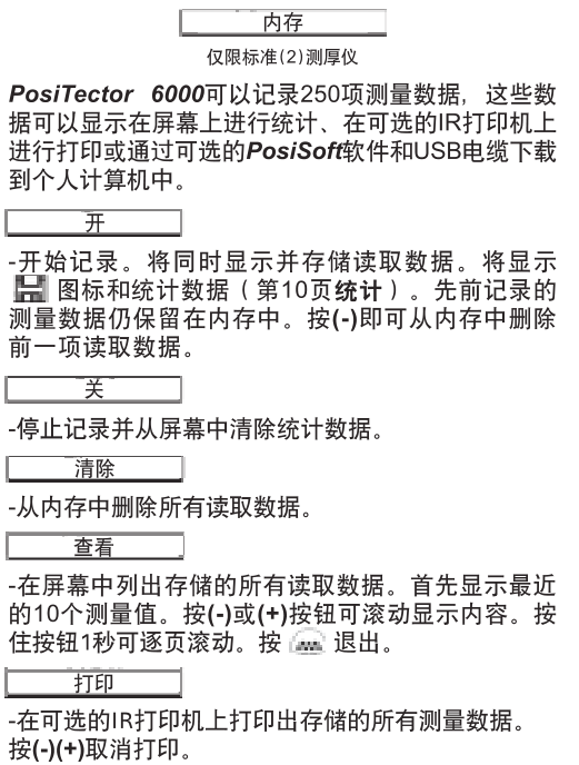
Cut down the measurement data stored in memory
You can download (batch) measurements stored in the gage's memory to your computer via the optional PosiSoft software and USB cable. Once the download is complete, the in-memory measurement data is not deleted, PosiSoft@ enables you to enter notes and instructions, print histograms and basic charts, and implement data management, as well as export the read data to a document or spreadsheet.
Statistical functions
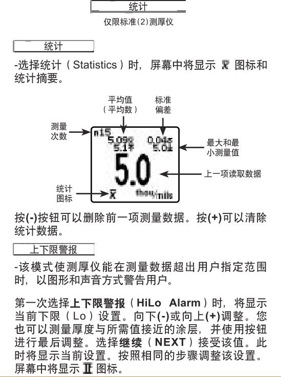
At this point, the measurement data is compared with the range you specify. If the measurement is within this range, the gauge will beep twice and flash green, if the measurement is low (Lo) limit, it will emit a bass sound, if the measurement is above the upper limit (Hi), the indicator will flash red. Press (+) to clear the upper and lower limits (HiLo) to read data.
Note: During the Reset process, make sure the gauge is away from the metal.
Split probes
The Split Transducer Thickness Gauge consists of a Thickness Gauge main unit and a transducer, and provides interchangeable transducers in a variety of sizes. Each transducer retains its own unique calibration information, and any transducer can be used with all gage hosts, to remove the transducer, turn off the gauge and position it horizontally
Pull the plastic probe connector (in the direction of the arrow) to remove it from the gage mainframe, and when the PosiTector 6000 is turned on, it will automatically determine the type of probe connected and perform a self-test. When the probe is close to the metal, it will "sense" and make a measurement attempt every 2 seconds, and when it is far away from the metal, the gauge will stop inducting, and if there is no operation within 3 minutes, the gauge will automatically shut down.
The continuous measurement function is only available for all readings that are placed on small surfaces or irregularly shaped surfaces after careful measurements, and before the probe touches the surface being measured. Do not drag the probe to the side.
Standard probes
These constant-pressure, stainless steel probes are completely sealed and waterproof – making them suitable for underwater operations. Pinch the 2 knurled rings on the probe and press down on the spring-loaded sleeve on the outer side. W
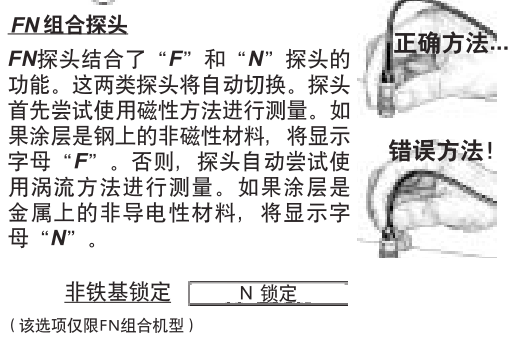
For routine measurements on non-ferrous substrates, select N Lock, which uses only the eddy current method when measuring with the probe, which can reduce measurement time and extend battery life.
N Lock is also suitable for measuring substances such as coatings outside thick steel plates. W
Optional accessories
We offer a variety of accessories to help you get the most out of your PosiTector 6000 Layer Gauge. W
temperature
Operating Range: +32 to +120°F (0 to +50°C)
The Posifector 6000 automatically compensates for the temperature, so wait a few moments for the probe to reach the ambient temperature before you start the measurement.
Ignore the first measurement of the temperature and make sure the probe is separated from the surface for 1 second between adjacent measurements when measuring a surface where the temperature is significantly confined to or lower than the ambient temperature.
Pass: Ferrous matrices with a limit temperature between 150 and +450°F (-100 and +230°C) can be measured using the PosiPen8. It is suitable for measuring small, hot, or hard-to-reach surfaces.
Troubleshooting
Our website provides some of the most frequently asked questions received by the customer service department and their possible causes, most of which can be solved using Reset (page 11).
The product is sent for repair
Before sending the gauge back for repair
1. Please follow the correct polar direction and put a new alkaline battery into the battery compartment.
2. Check whether the tip of the probe is sticky with dirt or damage, and the probe should be able to move up and down at will.
3. Perform a Thickness Gauge Reset (page 11)
4. Place the calibration finger on a metal ("F" or "N", ferrous or non-non-ferrous depending on whether the gauge is "F" or "N", ferrous or non-ferrous) uncoated substrate and measure.
If you need to return the gauge for repair, please provide a detailed description of the fault and the results of the measurement, if any, along with the gauge, your company name, company contact, phone number, and fax number or email.
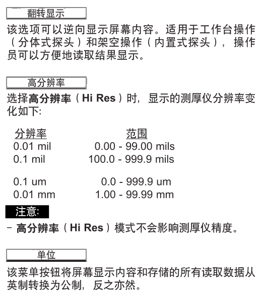
Technical data
Posifector 6000Gauge host size:
5.75 x 2.5 x 1.2 inches (146 x 64 x 31 mm)
Battery life: 50 hours of continuous use/36,000 data readings. W