As for the application introduction of computer real-time control of Tensile Testing Machine, this article is based on the control principle of hydraulic Tensile Testing Machine, and on the basis of analyzing its system structure and control characteristics, using the object-oriented Visual C++ programming language, a set of computer real-time The control method and program are very effective in solving the problem of the time lag problem on the system, and reducing the fluctuation of the load of the hydraulic components, thereby reducing the hydraulic shock of the entire system, making the equipment run smoothly, very effective The expected life cycle of the equipment is extended.
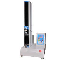
The Tensile Testing Machine involved in this article is an experimental equipment used in the construction of power transmission and transformation to test the reliability of various wires and connectors used in the project. In the test, there are strict requirements on the loading method, time and accuracy. At the same time, the force value range of the experiment is relatively large. Therefore, this equipment adopts the electro-hydraulic proportional servo system as the pulling force drive part, and utilizes the characteristics of high power density, fast response and stepless speed regulation of the hydraulic system to meet the requirements of the test. How to solve the hysteresis phenomenon caused by the leakage of the hydraulic system, the elastic deformation of the specimen during the stretching process and the slippage relative to the holder, and the long loading time are the key problems to be solved by the equipment control technology.
1 Composition and control principle of Tensile Testing Machine
The original control method of the whole system is: before the pulling force reaches the set pulling force, the output signal follows the step size set by the program. As the test time increases, the pressure in the oil cylinder also increases continuously. When the pulling force reaches the set pulling force, record the output signal. Control the signal value (for later compensation control), and output the control signal 0, at this time, the proportional valve is closed, and the oil pressure in the cylinder is maintained by the hydraulic control check valve. When the pressure in the oil cylinder decreases due to internal leakage, causing the tensile force on the test piece to decrease to the set allowable value, output the original recorded control signal value, restart the proportional valve, and replenish oil to the oil cylinder. After the pressure holding time reaches the set value, the direction is reversed immediately, and the proportional valve supplies oil to the other chamber of the oil cylinder, driving the oil cylinder to return, and the return pressure is determined by the original recorded control signal value. In this way, the control principle is relatively simple, but due to factors such as frequent start/close of the proportional valve, wear of the hydraulic control check valve and sudden change of direction of the oil cylinder, the service life and reliability of the system are significantly reduced, the set pull force is relatively small, and the return speed is very low slow.
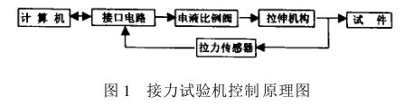
In order to solve the above problems, we designed a microcomputer real-time control device as shown in Figure 1, which consists of the following five parts:
⑴The computer is the control core of the whole device, and completes the real-time interrupt control of the system;
⑵The interface circuit is an ISA standard interface board, which is used to complete A/D, D/A conversion and I/O signal transmission;
(3) The tensile mechanism clamps and stretches the specimen, which is the main structural part of the Tensile Testing Machine;
⑷The tension sensor converts the tension signal into an electrical signal and feeds it back to the computer after A/D conversion;
(5) The hydraulic system is an electro-hydraulic proportional servo system with the electro-hydraulic proportional valve as the core, and the pressure of the system can be adjusted by changing the input voltage. The opening of the electro-hydraulic proportional valve is controlled by a computer. By adjusting the opening of the valve to change its overflow flow and thus change the working pressure of the system. According to the work requirements, the tension machine has two working modes
Static load test and rated load test, the static load test only needs to apply a large enough tensile force to break the specimen, and record the loading curve and the maximum tensile force; while the rated load test is to continuously increase the tensile force of the specimen according to a certain loading method. When the tensile force reaches the set force value, keep the pressure for a period of time and then unload to judge the load-bearing capacity of the specimen.
The system control host uses a general-purpose microcomputer with PentiumⅢ as the processor, and the HK-33 interface board uses a 12-bit A/D converter AD574 to form 16 analog measurement channels; a 12-bit D/A converter DAC1210 forms two The typical conversion time of the A/D converter is 25μs, the conversion voltage range is 0-10V, the conversion time of the single-channel system is about 50μs, and the sampling time of this system is 1ms, and its conversion speed is completely Can meet the control requirements. Among the 18 channels of the HK-33 interface board, only two D/A channels and one A/D channel are used, one D/A signal is used to control the electro-hydraulic proportional valve, and the other is used to control the hydraulic pressure changer. Directional valve; A/D channel is used to collect the force value signal of the tension machine in real time. The port addresses occupied by the two D/A channels on the microcomputer are 2C9H-2CBH, and the port addresses of the A/D channels used are 2C8H, 2CCH, 2CDH and 2CEH.
The control program introduced in this paper is written in Visual C++, an object-oriented programming language based on the Windows98 platform, and controls the entire test process according to the event-driven method. The input of test parameters and the control of the experimental process are intuitive; the calculation speed is fast, the control is sensitive, and the calculation accuracy is high. In the program, according to the actual needs, set the sampling clock cycle to 0.01s. In each clock cycle, the computer reads the current force value through the A/D port, compares it with the set maximum force value, and calculates the value according to the two values. To determine the current good control signal value, output through the D/A port to realize the automatic control of the hydraulic signal.
2 Control program design
During the tensile test, the computer sends out a control signal to control the pressure of the hydraulic system and the tensile force of the oil cylinder after D/A conversion. Theoretically speaking, the magnitude of the tensile force and the magnitude of the control signal should be proportional. The elastic deformation of the clamp and the slippage between the fixture and the specimen make the change of the tension seriously lag behind the change of the control signal value, and the system will have an obvious time lag, so the increase of the control signal (and the oil pressure in the cylinder) and the tension It is impossible to increase the synchronization. When the pulling force reaches the set value, the control signal D given by the microcomputer must be greater than the D/A value corresponding to the set pulling force at static time. The faster the loading speed, the greater the error. In order to solve this problem, improve the rapidity and stability of the control system. In the control program, the loading process is divided into three steps: in each time period (which can be set as an integer multiple of milliseconds by the program), (1) before the pulling force is less than 0.9 times the set force, use a relatively large Incremental step, increase the control signal; (2) After the pulling force is greater than 0.9 times the set force, use a relatively small incremental step, increase the control signal to avoid overload; (3) After the pulling force reaches the set force, pass Differential control, that is, the difference between the actual measured force value and the set tension value determines the increase or decrease of the control signal. Through the test, a set of static tension-control signal value list functions can be tested, and each test can be interpolated to obtain the static control signal DOBJ corresponding to the set tension value, which is used as the initial value of the differential control during the pressure holding period. value. In order to shorten the loading time and improve work efficiency, an initial value D0 of the control signal is added to the program. The loading starts from D0 instead of 0 in each test, and approaches the D/A value corresponding to the set tension value as soon as possible.
在保压期间, 比例阀不关闭, 微机输出给比例阀的控制信号 D保持相对稳定, 由比例阀直接保压。并According to每个采样周期所测得的当前力值, 来动态调整比例阀的控制信号 D。
保压结束后,结束试验即卸载也分为两步: (1) 在每一个时间周期, 输出信号逐步减小, 油缸内液压力也逐步减小; (2 ) 当输出信号 (和油缸内液压力) 接近于0时, 再发出换向信号, 控制比例阀换向, 驱动油缸回位, 减小液压冲击; 回程时输出信号值为常量, 回程速度不受设定拉力影响;
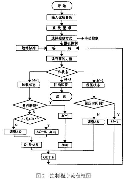
控制程序流程框图如图2所示, 其中, M为描述工作状态的开关变量, D为 D/A控制信号值, F为当前力值, F0为试件设定拉力值。 在控制算法上, 作了比较大的优化, 拉力波动更小,避免液压系统频繁换向; 在试验结束时, 通过延时、 换向、 增压回位元控制过程,减小液压系统的冲击,提高设备的寿命。
该程序采用流行的文档/视窗模式,先利用 Visual C ++提供的 MFC AppWizard生成初始的文档/视窗型框架,再用 Visual C++的资源编辑器建立一个对话框,并在其中设置输入各个参数所需的控件, 然后派生出一个管理输入参数的视窗类,连接到 CmainFrame类中,再对窗口风格进行相应的设置, 即可完成界面设计。
读入力值使用_inp(address)函数,其中address是A/D口的地址;输出 D/A控制信号使用_outp(address1 , intD)函数, 其中 address1是 D/A口的地址, D是D/A控制信号值。 在该程序中设置了软件置零功能, 试验人员只需在传感器不受力时, 点击 《置零》 按钮即可设定零点,改由程序实现后, 避免了硬件调零操作上的不便, 并可消除试验过程中的系统误差。
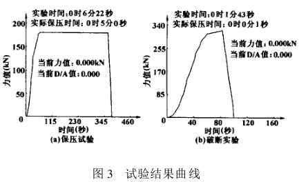
During the test, various test parameters (such as tension, holding time and rated load, etc.) can be set through the computer interface, and the control program automatically completes the control of each test link, test result output, Report printing and file management. Relying on the powerful system functions of Windows, the program has good stability and can avoid test failures caused by computer system failures. Fully meet the on-site production requirements, the control program running results are shown in Figure 3:
3 Conclusion
As a typical electro-hydraulic computer automatic control instrument, the hydraulic Tensile Testing Machine has brought a lot of trouble to the control system because of the serious time-lag characteristics of the system and strict restrictions on the overshoot. . After introducing the subsection differential control algorithm, this difficult problem has been better solved. Judging from the actual use of more than two years, the control program algorithm is feasible and the operation result is also reliable.