The electronic Tensile Testing Machine is mainly a test machine equipment controlled and measured by a computer, and is mainly used in the tensile testing of metal and non-metal materials. Tensile testing machines are widely used in quality supervision, scientific teaching and research, automobiles, construction materials and other fields. Electronic Tensile Testing Machine has the characteristics of accurate detection value, wide detection range and fast corresponding speed in the application of product quality testing such as tension, compression and bending. It can record the test data and record the maximum test force value according to the standard. , Fracture force value, yield force value, calculate the experimental data such as elongation at break and various strength values.
The electronic Tensile Testing Machine is mainly composed of a drive system, a control system, a measurement system and other structures. After the drive system is powered on, the microcomputer issues a beam movement command according to the value set before the test. The command controls the rotation of the servo motor inside the main engine through the servo control system, and drives the left and right screw rods to rotate after passing through the belt, gear and other reduction mechanisms. The crossbeam is driven up or down by the toothed nut inside the movable crossbeam. After loading the sample, the testing machine can obtain the corresponding signal through the load, strain and displacement sensors, and after the signal is amplified, the data is collected and converted through the A/D, and the data is transmitted to the microcomputer.
On the one hand, the microcomputer processes the data, and reflects it on the microcomputer display in the form of graphics and numerical values; on the other hand, it compares the processed signal with the initial set value, adjusts the movement of the crossbeam to change the output, and converts the adjusted output Passed to the servo control system, so as to achieve high control requirements such as constant speed, constant strain, and constant stress. The working principle of each component of the electronic Tensile Testing Machine is introduced below.
1 Measuring system
1.1 Measurement of force value
The measurement is realized by load cell, signal amplifier and data processing system. Commonly used load cells are strain gauge sensors. The so-called strain gauge sensor is composed of strain gauges, elastic elements and some accessories (compensation elements, protective covers, wiring sockets, loading parts), which can convert a certain mechanical quantity into an electrical output device. There are many types of strain gauge type tension and pressure sensors at home and abroad, mainly including cylindrical, spoke type, S double-connected hole type, cross beam type and other sensors. The quality of the load cell determines the accuracy and stability of the force measurement of the testing machine. At present, the electronic Tensile Testing Machine on the market generally uses S-type sensors for small force values, and generally uses spoke sensors for large force values. Common electronic Tensile Testing Machine load cells are 0.5 and 1, and the maximum allowable errors are ±0.5% and ±1%, respectively. The maximum test force generally does not exceed 20kN.
1.2 Measurement of deformation
It is measured by a deformation measuring device, which is used to measure the deformation of the sample during the test. Deformation measurement device, also known as extensometer, is an extensometer system composed of deformation sensors with different accuracy and deformation measurement unit of testing machine.
There are two chucks on the device, which are connected with the photoelectric encoder installed on the top of the measuring device through a series of transmission mechanisms. When the distance between the two chucks changes, the shaft of the photoelectric encoder is driven to rotate, and the photoelectric encoder There will be a pulse signal output, and then the signal will be processed by the single-chip microcomputer to obtain the deformation amount of the test.
1.3 Measurement of beam displacement
Its principle is roughly the same as that of deformation measurement, and the displacement of the beam is obtained by measuring the output pulse number of the photoelectric encoder.
2 drive system
It is mainly used for the beam movement of the testing machine. Its working principle is that the motor is controlled by the servo system, and the motor drives the screw to move through a series of transmission mechanisms such as a gearbox, so as to achieve the purpose of controlling the movement of the beam. By changing the rotation speed of the motor, the moving speed of the beam can be changed. Some motors of electronic Tensile Testing Machines are ordinary three-phase motors or variable frequency motors. This kind of motor is controlled by analog signals, which has slow response, inaccurate positioning, and narrow speed range. If there is high speed, there will be no vulgarity; Inaccurate speed control. The other motor is a fully digital AC servo motor, which adopts full digital pulse control and has a wide range of speed regulation, up to (0.001-1000) mm/min, accurate control and positioning, fast response, and can be added to full speed in 0.01 seconds. Some transmission mechanisms of electronic Tensile Testing Machines use reducers, some use ordinary belts, and some use full-arc synchronous belts. The screw is the part that drives the movement of the load cell. Some electronic Tensile Testing Machines on the market use a T-shaped ordinary screw, and there are also gapless ball screws. The T-shaped ordinary screw rod has relatively large clearance, relatively large friction force, and short service life.
3 control system
As the name implies, the control system is the system that controls the operation of the testing machine. The main controller has a microcomputer (using a PC) or a microcomputer (using a single-chip microcomputer or PLC, etc.). The operation of the testing machine can be controlled through the console, and the status of the testing machine and various test parameters can be known on the display screen. If the machine is equipped with a computer, the computer can also realize various functions, perform data processing and analysis, and print test results. The communication between the testing machine and the computer generally uses the RS232 serial communication method, and communicates through the serial port on the back of the computer. The computer is used to collect and analyze data. After entering the test interface, the computer will continuously collect various test data, draw test curves in real time, and automatically calculate test parameters and output reports.
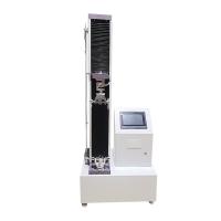
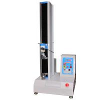
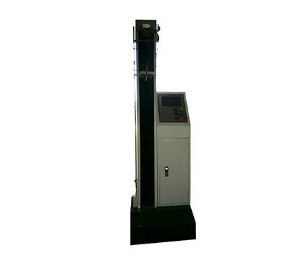
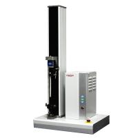
The following is an overall introduction to the body of the electronic Tensile Testing Machine. The host part is the transmission part of the electronic Tensile Testing Machine. It provides a standard experimental space for the sample. Tensile aids need to be installed above the host to perform tensile tests. It mainly includes fixed beams, moving beams, load cells, workbenches and bottom plates. The workbench is the main support of the main machine. All transmission systems are installed on the workbench. The motor reducer system is installed at the lower part of the workbench. The output of the reducer is connected to the screw rod installed on the workbench through a synchronous toothed belt. , the rotation of the motor drives the screw to rotate. A screw nut is installed on the screw rod, and the screw nut and the moving beam are fixed as a whole. When the screw rod rotates, the moving beam can move up and down. All the experimental processes are realized by moving the moving beam up and down. The load sensor is fixed on the moving crossbeam by screws, and the fixed crossbeam is the fixing part of the connecting part of the main engine and the stretching aid. The electrical control part includes two parts: the strong electric operation button and the electrical control box. The strong current operation panel includes a motor switch and an emergency stop button, and together with the strong current panel constitutes the strong current control part of the system. The travel limit device is realized by approaching the moving beam through the photoelectric travel switch, and the position is adjusted properly before the experiment to protect the machine.