Regarding the equiaxial tensile test method and simulation of hyperelastic membrane, this paper mainly introduces the application principle and operation method of the equiaxial symmetric tensile test device of hyperelastic membrane material, and analyzes and discusses the equiaxial tensile test conditions and data processing, and then uses the finite element software ABAQUS to simulate three isometric tensile methods: equiaxial centrically stretched, free tensile with unfixed corner tensile points, and isometric tensile with fixed corner points. From the experimental research results, it is understood that the equiaxed tensile method with fixed corner points has a small error in a large tensile test range, which can meet the requirements of material testing.
Acrylic rubber is an electroactive polymer with high elasticity and high strain energy density, which has received extensive attention in the fields of bionic robots, artificial prosthetics, and fluid control. Acrylic rubber is a superelastic material, and its constitutive relationship plays an important role in the design and optimization of its driver. For hyperelastic materials, the energy (work) stored in the material depends only on the initial and final states of the deformation and is independent of the deformation (or load) path, so the easiest way to describe the stress-strain constitutive relationship of similar hyperelastic materials is often with the help of the strain energy function.
The constitutive models of common hyperelastic rubber materials are mainly divided into three forms: Mooney-Rivlin type, Yeoh type and Ogden type according to different strain energy functions, and the model parameters can be obtained by experiments, and the test methods are usually compression and tensile. The compression method is generally uniaxial compression, while the tensile method is uniaxial, planar, equiaxed, etc. The uniaxial compression test is often used to replace the uniaxial compression test with complex stress states such as compression and shear due to the friction between the contact surfaces, which makes the results of the actual test inaccurate.
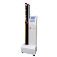
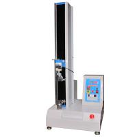
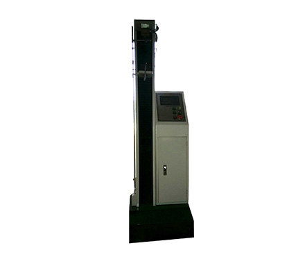
In the study of equiaxial tensile of superelastic rubber, foreign researchers have developed some corresponding equiaxial biaxial tensile testing equipment (or methods). Wissler et al. ignored the change of radial force when the driver applied voltage in the study of pre-stretched circular drivers, and studied the biaxial (multi)axial characteristics of dielectric hyperelastomers, but the model parameters were still derived from the results of uniaxial tensile tests. Sasso et al. designed an inflatable (liquid) expansion test device based on optical methods, which accurately measured the strain by moving the camera focus, which was simple in structure and was a typical device for studying the biaxial tensile of thin films, but there were problems of leakage and difficult to control the strain during the test. Miller has designed a device for radial tensile of slotted circular sheets, which can be used for isometric tensile test analysis, which can well control the strain process, but requires the production of special slotted round specimens, and the test structure will affect the test accuracy of the "small" stiffness hyperelastic membrane material due to factors such as chuck weight and friction. Obata et al. introduced a device for equiaxial stretching of square specimens, which can directly perform biaxial stretching on the membrane (sheet) material and simulate the biaxial tensile stress state of the center, which has been widely used, but it belongs to "asymmetrical" tensile tensile, and a pair of force transducers need to be configured in two stretching directions for tensile force measurement. In this paper, an equisymmetrical tensile platform was designed, and the isoaxial tensile test was carried out on the VHB4910 acrylic film material of 3 M, and finally the isometric tensile test method was simulated by the finite element analysis software ABAQUS (related instrument: Tensile Testing Machine)
1 Constitutive model of hyperelastic materials
Mooney-Rivlin strain energy function: W=C10(I1-3)+C01(I2-3) (1)
where C 10 and C 01 are the material parameters, and W is the strain energy function determined by the first invariant I 1 and the second invariant I 2 of the left Cauchy-Greene deformation tensor.
2. Isometric tensile test method and principle
2.1 Isometric tensile test method
In this paper, square membrane samples are used for equiaxial tensile testing of materials.
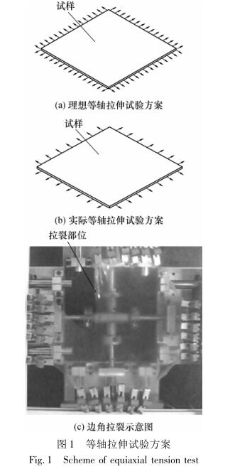
The equiaxed tensile test scheme is shown in Fig. 1(a), in which a uniform tensile stress is applied around the perimeter of the specimen to deform it uniformly. Because of the mechanical clamping required during tensile, this kind of satisfactory tensile test cannot be achieved under actual test conditions. The actual equiaxed tensile test scheme can only be an approximate simulation, that is, the equiaxed free tension is carried out by applying concentrated force at the four peripheral distribution points of the specimen, that is, each tensile point is not constrained during stretching, as shown in Fig. 1(b). In fact, when the isometric tensile test is carried out according to Fig. 1(b), there is shear force at the 4 corner tensile points, and due to friction and other factors during tension, the corner points cannot meet the requirements of "fast" lateral movement, which will produce a large strain between the corner points, and if no measures are taken, it is easy to crack when the elongation is large. The corner cracking of the actual free stretching is shown in Figure 1 (c). Therefore, when performing an equiaxed tensile test, it is necessary to take measures to prevent tensile cracking at the corners. For this reason, the actual stretching scheme should be treated as follows:
(1) Take measures to prevent cracking at the corners;
(2) When stretching, each stretching point should be able to meet the tangent line along the edge of the sample
freedom of movement;
(3) There are enough tensile points to make the specimen evenly stretch and deform;
(4) The selection of the stress-strain measurement range should be considered in the deformationHomogeneous area.
2.2 Working principle of equiaxed tensile test bench
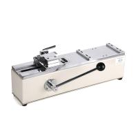
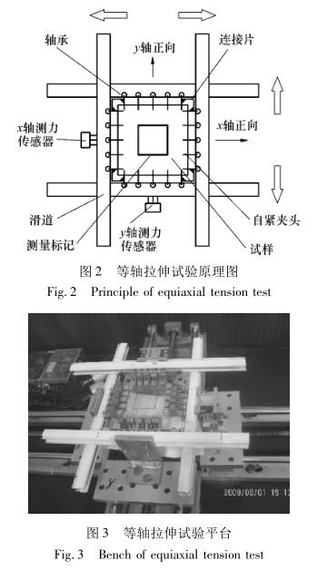
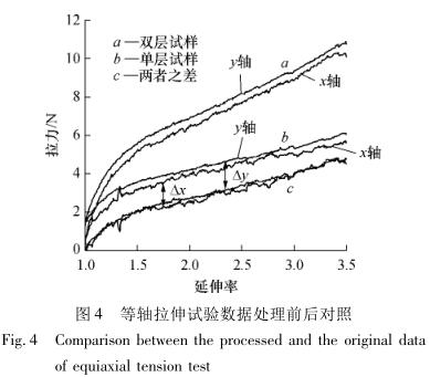
The working principle of the equiaxed tensile test bench is shown in Figure 2. Two pairs of reverse lead screws are driven to rotate by a stepper motor (not drawn in the figure), so that two pairs of slides on the x and y axes are driven to stretch at an equisymmetrical uniform speed along the x and y directions shown in the figure. The specimen is clamped by 20 evenly distributed self-tightening chucks around the perimeter. At the 4 corners of the membrane sample, 4 pairs of self-tightening chucks are connected by flexible connecting pieces, that is, the equiaxed tensile test method with fixed corner points. When stretching, the self-tightening chuck moves along the slideway with the bearing at the rear of it. The actual strain is measured by the strain at the mark shown in the caliper measurement diagram as two pairs of perpendicular marker lines about 40 mm apart. During the tensile test, the X and Y axial load cells installed next to the slideway on one side of the X and Y axes respectively detect the tensile force synchronously, and realize (timed) fixed-point tensile force data acquisition through software. The equiaxed tensile test platform is shown in Figure 3. In order to reduce the influence of the clamping area on the tensile deformation, the clamping contact between the self-tightening chuck and the membrane is in line contact with a width of about 1 mm.
3. Equiaxed tensile test data processing
3.1 Equiaxed tensile test conditions
To eliminate the effects of the Mullins effect, a formal tensile test is performed before eachIn order >to eliminate the influence of viscoelasticity, the tensile force data needs to be collected in a quasi-equilibrium state or at a very low tensile rate. In this paper, the latter method is used, and the stretch rate is "·=3. 54×10-4 s-1[10].Isometric tensile tests and data acquisition can be performed after pre-tension. Due to the existence of errors in the acquisition process, the collected data needs to be processed before it can be used for analysis.
3.2 Test data processing
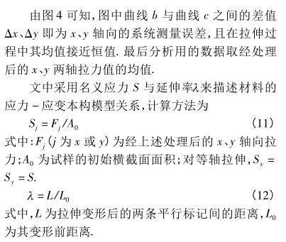
The above isometric tensile test is performed on a horizontal plane, self-tighteningThe self-weight of the chuck, the manufacturing error of the lead screw slide of the test bench, the friction between the slideway and the bearing, and the zeroing error of the load cell will cause errors in the measurement data and affect the accuracy of the subsequent analysis of the data. In order to eliminate the systematic error of measurement, the single-layer and double-layer films with the same plane size were selected as the specimens for multiple tensile tests. During the test, the tensile conditions (i.e., tensile rate and elongation) are consistent each time, and the influence of systematic errors is eliminated through the error cancellation principle to improve the measurement accuracy.
The equiaxed tensile test uses two kinds of specimens: single-layer film and double-layer film. singleThe laminar specimen is a square membrane of 90mm×90mm×1 mm, and the double-layer membrane specimen is two monolayer membranes stacked together. Under the same tensile conditions, the real tensile force of the single-layer film specimen and the double-layer film specimen is Fs and Fd, then Fd=2Fs. Assuming that the measured tensile values are FCS and FCD respectively, considering the systematic error, theoretically the above values have the following relationship:
Fcs=Fs+Δ (9)
Fcd=2Fs+Δ (10)
Subtract the two formulas to obtain Fcd- Fcs= Fs, i.e., for the actual calculation and analysis
The tensile value should be the difference between the tensile value measured by the two tensile values of the single-layer and double-layer specimens, so that the influence of systematic error on the measurement accuracy can be effectively eliminated. The x-axis tensile test data obtained by the tensile test of the above two specimens and the processed data are shown in Figure 4.
4. Simulation analysis
Due to the tensile method with fixed corners, the deformation is unevenUniformity will have an effect on the tensile results, and the finite element analysis software ABAQUS is used to analyze the tensile results as a control.
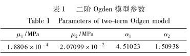
The collected data are processed according to the above method, and finally the parameters of three constitutive models can be obtained by fitting the data of equations (6)-(8) by using the global optimization algorithm by the mathematical optimization software 1 stopt[11]. After analysis, the second-order Odgen model has the highest accuracy[10], and the parameters of the second-order Odgen model obtained after fitting are shown in Table 1.
After the material model is selected and the model parameters are determined, the simulation analysis can be carried out to verify the accuracy of the test method. As a general-purpose finite element software, ABAQUS has its own unique features when performing nonlinear analysis.
The equiaxed tensile test imitates Allah's comparative analysis of the above three tensile methods. In the three simulation tests, the model parameters are based on the second-order Ogden model parameters fitted by the above experiments, and the finite element analysis model is meshed by 4-node shell element (S4R). In order to reduce the number of elements and simplify the calculation, a symmetrical 1/4 membrane sample was taken for analysis. The boundary conditions are that the left and bottom elements limit their displacements in the x and y directions, respectively, and apply uniform linear displacements to the top and right edges and the extrusion points, respectively, with elongation" = 4, as follows:
(1) Equiaxed centrically stretched to apply equal uniform linear displacement loads to the top and right edges.
(2) Free stretching with unfixed corner stretch points 3 points are evenly distributed on the top and right edges, and uniform linear displacement loads are applied along the tensile direction x and y respectively.
(3) Equiaxed tensile with fixed corner points (i.e., the test method in this paper)
The so-called "corner point fixation" refers to the fixed distance between the two stretch points at the corners in the x and y directions when stretching. During the simulation loading, three points are evenly distributed on the upper and right edges, and uniform linear displacement loads are applied along the tensile direction x and y respectively, and the distance between the two points at the corners is kept unchanged during the stretching, and the displacements of the two points at the corners are 45° respectively with their main tensile directions.
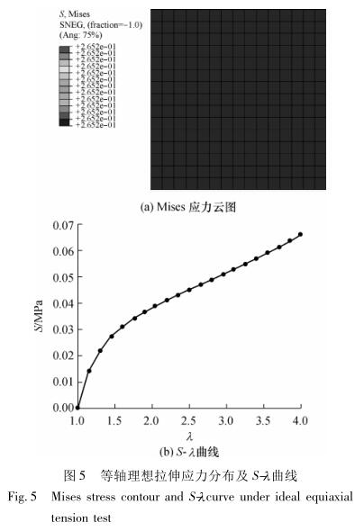
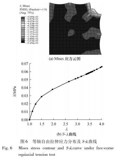
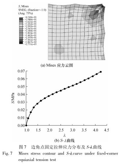
Figure 5-7 shows the Mi-ses stress contour and S-" relationship curves obtained by finite element analysis of the above three tensile methods.
The Mises stress contour diagram reflects the stress distribution during the tensile test. As can be seen from Fig. 5 (a), the stress distribution is uniform when the equiaxed center is stretched. From Fig. 6 (a), it can be found that when the elongation is large, the stress at the corner is too large, there is shear stress, and the mesh distortion is serious, which is consistent with the above analysis results. Fig. 7 (a) simulates the tensile condition of the actual corner tensile point, and it can be seen from the Mises stress contour diagram that the tensile stress is unevenly distributed, and the maximum stress appears near the corner tensile point. The last two tensile stresses and deformations are relatively uniform in the vicinity of the center, which indicates that the method of taking the stress-strain values near the center of the above test data is reasonable.
In order to obtain the stress-strain relationship, the nominal stress S and elongation of the three tensile methods need to be calculated according to equations (11) and (12), where the tensile force is taken as the sum of the axial simulated tensile forces of each tensile point, and the obtained S-" relationship curves are shown in Fig. 5(b), Fig. 6(b) and Fig. 7(b). The above 3 types
The calculated S-" curve under tensile condition and the S-" curve simulated at the mark node (here the elements and nodes at the mark 20 mm from the coordinate origin along the x-axis are taken) are shown in Figure 8.
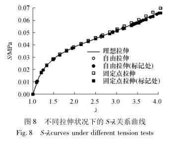
As can be seen from Figure 8, the S-" relationship curves are very close, and the imitation Allah tensile stress at the mark is basically equal to the centrified tensile stress, indicating that the selection position of the measurement mark is suitable. In the tension of fixed corner points, the calculated nominal stress is larger than that in other cases because the tensile point of the corner is fixed, which causes excessive distortion of the elements at the corners, and the overall tensile force is slightly increased. According to the simulation results, the maximum error of several curves occurs at the maximum elongation. At " = 4, the nominal stress error between the fixed stretch and the satisfactory tension at the corner stretch point is about 3. 92% of the above analysis shows that in a large tensile range, the fixed tensile method with fixed corner tensile points has a small error, which can meet the requirements of material test analysis.
5 Conclusion
In this paper, the operation method and principle of the isoaxial tensile test of an acrylic rubber superelastic membrane material are mainly examined, and the collected isometric tensile test data are processed by using the error cancellation method to enhance the analysis accuracy. Finally, combined with three equiaxed tensile test methods, the influence of uneven deformation at the corners on the tensile accuracy was analyzed by using the finite element software ABAQUS. The results of finite element analysis show that the error of the equiaxed tensile method with fixed corner points is small in the large tensile range "(≤4), which can meet the requirements of the equiaxed tensile test of hyperelastic materials.