At present, the physical and chemical laboratory has received many tasks for the destructive tension test of the steel cable, 44 batches in the first half of 2013 alone, and the product design has changed the ball end of the steel cable of the xx machine, so the original test of the physical and chemical laboratory Tooling and test methods are no longer applicable to the existing cable failure tensile test. It is necessary to redesign the test tooling and readjust the test method.
1. Introduction of cable failure tensile test
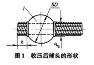
1.1 Shape and size of steel cable spherical joint
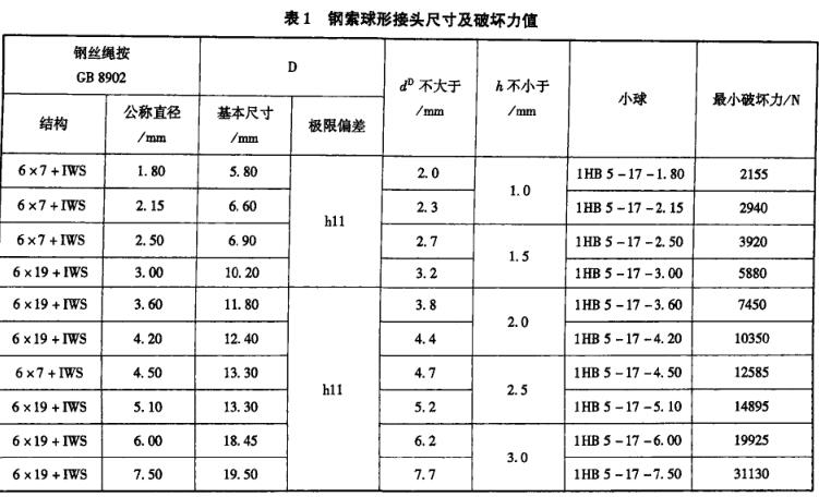
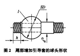
The steel cable and the ball head are assembled and compressed according to HB5-17. No cracks are allowed in the ball head after pressure reduction, the wire rope should not have broken wires, and the surface of the ball head should be smooth. The shape and size of the ball head after pressure reduction are shown in Figure 1 and Table 1.
1.2 Destruction tensile test
According to the regulations in HB5-17-1990: each batch of crushed ball-end steel wire ropes (not less than 3 pieces) shall be subjected to a destructive test, and the damage shall not be lower than the minimum destructive force specified in Table 1. If the root is broken or the ball head is pulled off under the load less than the breaking load, then this batch shall not be delivered.
What needs to be pointed out here is that the design has changed the cable ball head of the xx machine, and a guide sleeve has been added to the tail of the ball head, as shown in Figure 2. As a result, the original test equipment and test methods in the physical and chemical laboratory are no longer applicable to the existing tests, which increases the difficulty of the test.
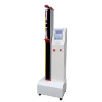
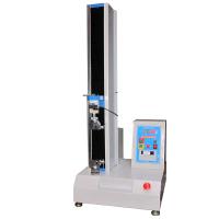
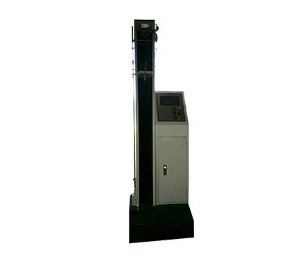
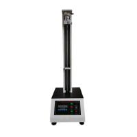
2 Solid head structure of electronic Tensile Testing Machine
Tensile test is one of the most basic and commonly used tests in mechanical performance test. Tensile test mainly provides data on the strength and plasticity of metal materials under uniaxial tension. During the test, various gripping devices for measuring loads applied by the testing machine to the specimen may be used.
The clamping device of the electronic tensile machine is divided into two parts: the upper chuck device and the lower chuck device. During the test, the upper and lower chucks of the testing machine respectively clamp the clamping parts at both ends of the sample. At the same time, the chuck applies axial tensile stress to the sample at the same test speed, and the axis of the sample should be consistent with the axis of the chuck of the testing machine.
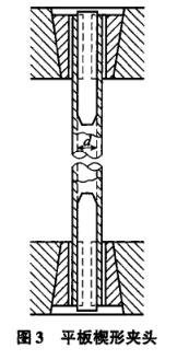
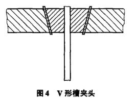
There are usually two types of collets equipped with electronic tensile machines: flat wedge collets and V-groove central collets. As shown in Figure 3 and Figure 4, the specifications of the collets of electronic tensile machines are related to the thickness or Matching diameters, flat wedge grips are used to grip rectangular tensile specimens of various thicknesses, and v-groove grips are used to grip circular tensile specimens of various diameters.
It can be seen from the above that the electronic tensile machine can only hold plate-shaped samples or circular samples, and the cable ball joint itself cannot be connected with the testing machine. Its failure tensile test can only be completed by connecting the test tool with the electric Tensile Testing Machine.
3 Determination of test tooling
3.1 Test tooling before improvement
原有的试验工装结构比较筒单,如图5所示,钢索接头的上半部通过试验工装与电子拉力机的上夹头相连。钢索接头的下半部是用砂纸作为保护,直接与电子拉力机的下夹头连接。原有的试验工装有如下缺点:
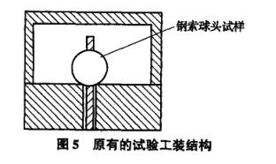
(1)xx型机钢索接头的结构更改后,球头尾部增加了引导套,引导套的尺寸大于工装上穿入钢索部分的尺寸,钢索接头无法装入此试验工装。此试验工装对更改后的钢索接头破坏拉力试验已不适用。
(2)此试验工装结构的安全性较差,没有保护装置。试验过程中钢索球头一旦拉脱,球头飞出,有可能砸伤试验人员。
(3)此试验工装的互换性较差,钢索直径过大或过小的试验均不能用此工装进行。
(4)钢索接头的下半部没有试验工装作为过渡,通过砂纸保护直接与拉力机的下夹头连接。此方法在试验过程中,钢索被下夹头的夹具夹紧,夹持部分的钢索有可能断丝,影响试验结果,此方法的试验性较差。
3.2改进后的试验工装
针对上述现有试验工装的优缺点,对现有试验工装的缺点进行逐一改进,设计并制造了新的试验工装,如图6所示。
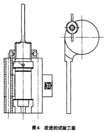
此工装方案的优点是:
(1)工装与电子拉力试验机上夹头连接部分为钢索球头设计了保护單,此部分工装分为前后两部分,用蝶形螺母和销钉连接。试验时将试验件放入工装后,用蝶形螺母和销钉将前后两片工装连接并锁紧,试验过程中,钢索球头在工装的保护罩中,如果钢索球头被拉脱,球头不会飞出,避免砸伤事件的发生。
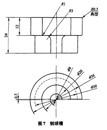
(2)针对钢索规格、直径不同,且与之相配的球头直径大小也不同的情况,设计并制造了放置钢索球头的3种规格的钢球槽,同时考虑到xx型机带引导套的钢索球头,钢球槽设计成抱胎的形式,以方便试验件的装卸。如图7所示。
(3)参考线材试验用的挽勒装置,设计了用于钢索与电子拉力机下央头连接的连接件。试验时将钢索端头缠绕在连接件上,用蝶形螺母和销钉将钢索锁紧,这样在试验时,电子拉力机下夹头不直接与钢索连接,夹持的是连接件的夹持部分,保证试验过程中钢索不会断丝,保证试验结果的准确性。
(4)总结以往的试验经验,试验工装与电子拉力试验机上、下夹头连接部分的材料硬度不能太高。如果材料硬度太高,在试验过程中,可能由于试验机的夹持力不够而产生打滑现象。故此部分采用退火材料,并双面加工成网纹结构以增加工装夹持部位与试验机夹持部分的摩擦力。
4试验程序
4.1试样
接收试样,检査试样表面质量及试样数量。
4.2试验步聚
(1)检査试验请托单和组件制造指令请托试验内容的一致性。
(2)进入试验程序,编制试验文件。输入钢索球形接头试样的相关信息。
(3)在钢丝球头的尾部划上标记,选择与钢索球头相配的钢球槽,将试样放入保护罩中,用蝶形螺母锁紧销钉。
(4)将试验工装的上半部分与试验机的上夹头连接。
(5)将试验工装的下半部分与试验机的下夹头连接。
(6)钢索的另一端裝入工装的连接件,用蝶形螺母锁紧。
(7)设定试验的加载速度,并按试验请托单中的规定设定试验的最大拉伸载荷。
(8)开始试验,观察试样在加载过程中的变化。
(9)试验载荷在到达最大拉伸载荷时,试验机停止加载,一个钢索球头接头的破坏拉力试验结束。
(10)卸去载荷,打开拉力机的气动上、下夹头,将试样从试验工装内卸除,更换另一个试样。
(11)将装配好的试样与试验工裝安装到拉力机上,开始第二件试样的试验。
(12)待试样的全部试验完成后,试验结束。
5试验结果的评定
理化实验室用新制的钢索试验工装对钢索球头接头进行破坏拉力试验,对钢索球头施加轴向的拉伸载荷,达到图样规定的载荷时,接头质量完好,.球头未拉脱,钢索未拉断。从而得出结论,试验工装完全满足试验需要,破坏拉力的试验结果完全符合图样要求。
6试验成果
Through this test task, the experimenters in the physical and chemical laboratory summed up the test experience, changed the structure of the tooling, refined and designed the tooling, and successfully completed the tensile test of the steel cable ball head with the new tooling. In terms of designing test tooling, the personnel in the physical and chemical laboratory developed new ideas, and a set of test tooling can be used to complete the destructive tension test of steel cable ball heads of various specifications, which not only saves test tooling, but also greatly reduces the operational difficulty of the test personnel. In terms of testing, the newly made test tooling has increased the safety of the test, and adjusted the test method. While successfully completing the test task, it has accumulated and expanded the test experience in this type of destructive tensile test, providing a basis for similar tests in the future. Assure.