Clamping principle for tensile testing
Aiming at the column test sample of the common ductile metal tensile test, the basic conditions that need to be met by the clamping section and the fixture of the specimen during the tensile test are derived by analyzing the force and failure mode of the tensile specimen, and the constraints that need to be met between the initial preload pressure, the system friction characteristic parameters and the geometric size of the specimen and the material property parameters are given in combination with the two typical tensile tests of the actual specimen, the material yield strength test and the ultimate strength test. The purpose is to establish a deterministic analysis model of the clamping principle, and to provide a basis for the formulation of test standards, the design of test equipment and specimens, and the test operation. At the same time, prepare for random analysis.
Tensile testing is the most widely used form of testing in quality inspection and material property testing research. The afterburner and test process of tensile test is simple and convenient, but the force of the tensile specimen clamping section and the factors involved in the test are very complex. For the ultimate stress test of materials and the ultimate tensile test of members of equal cross-section, it is necessary not only to analyze the force in the ultimate limit state, but also to consider the influence of random factors in the clamping process.
The clamping principle is the basic basis for the formulation of test standards, the design of test equipment and the design of specimens, and the test operation. It is also the basis for fixture design and test analysis. The effectiveness of tensile test clamping involves the structure of the testing machine, the shape and material of the specimen, and the purpose of the test. The study of clamping problems needs to be considered from the mechanical structure of the testing machine and the material mechanics of the tested sample. This is a work that is currently lacking, and it is not covered by various test standards and experimental instructions.
In this paper, the basic conditions that need to be met by the clamping section and fixture of the specimen during the tensile test are derived by analyzing the force and failure mode of the tensile specimen, and the relationship between the geometric size and the material performance parameters is given by combining the two typical tensile tests of the actual specimen, the material yield strength test and the ultimate strength test, and the relationship between the geometric size and material performance parameters that need to be met to restrict the initial preload pressure, the system friction characteristic parameters and the specimen is given. The purpose is to establish a deterministic analysis model of the clamping principle, and to provide a basis for the formulation of test standards, the design of test equipment and specimens, and the test operation. At the same time, prepare for complex stochastic analysis.
 1 Force analysis of tensile clamping
 1 Force analysis of tensile clamping
1.1 Analytical Model
Assuming that the sample material is uniform and continuous, the maximum bearing capacity is determined by the yield limit without considering the strengthening effect of the material in the clamping section. The geometry and dimensions are determined accurately, regardless of the impact of dimensional errors. The strength of the fixture is sufficient, and only the influence of the geometric parameters of the fixture on the force is considered in the analysis, and the damage that may be caused by the insufficient strength of the fixture material is not considered. In addition, the tribological characterization analysis is based on static friction.
1.2 Description of the tensile specimen
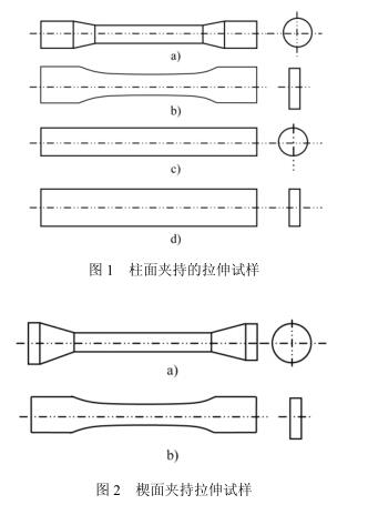
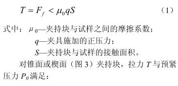
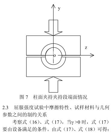
Common tensile specimens are divided into shapes, one is cylindrical (e.g., Fig. 1a), c)); The other type is the plate specimen (as shown in Fig. 1b), d)). where a) and b) are the standard specimen shapes for tensile testing of materials. Cylindrical or prismatic specimens of equal cross-sectional shape are used for wire or profile quality inspection (Fig. c, d)). According to the way of clamping force application, one is the cylindrical clamping specimen (as shown in Fig. 1), and the other is the wedge clamping specimen (as shown in Fig. 2). Cylindrical gripping specimens are tensile specimens that are clamped by friction generated by pressure perpendicular to the cylindrical surface. The clamping force of the cylindrical specimen acts on the torus surface, while the clamping force of the plate specimen acts on the contact plane. The wedge gripping specimen relies on the support force acting on the wedge surface to grip the tensile specimen. In this paper, the cylindrical clamping specimen is first studied.
1.3 Force analysis of tensile clamping
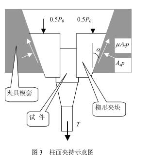
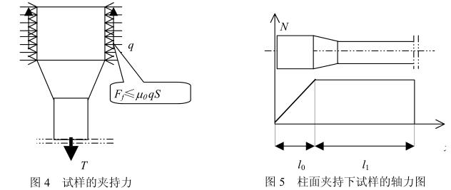
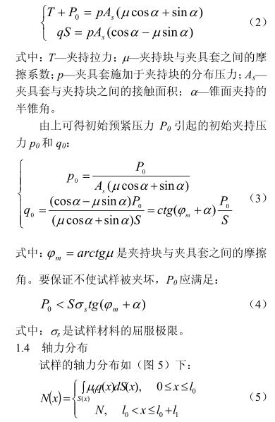
Considering that the cylindrical surface is clamped on the current testing machine, the sample is takenA wedge-shaped hydraulic mechanism (Fig. 3) is used, and the two clamps are theoretically parallel to each other. Therefore, it can be assumed that the force exerted by the clamping mechanism is uniformly distributed along the axis of the specimen.The friction provided by the clamping is balanced with the tensile force (Fig. 4), and the friction force needs to be less than the critical friction force, including:
2 Critical analysis of tensile specimens
2.1 Maximum pulling force
2.1.1 There are two failure modes at the clamping place and judgment criteria: one is that the specimen is pulled out of the fixture, and the other is that the material at the clamping place reaches plastic yield.
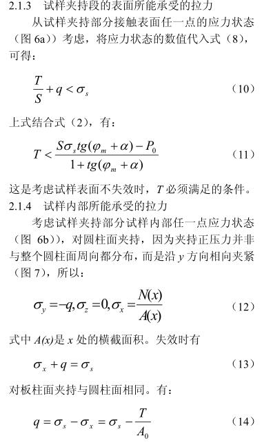
Considering pull-out failure, the friction force is characterized by reaching its maximum value. Considering the balance of tensile force and frictional force, it is noted that the uniform distribution of the clamping force is assumed that the clamping force should satisfy Eq. (1). Considering the plastic yield failure, according to the third strength theory, the maximum shear stress of the material at the clamping position of the specimen will satisfy:

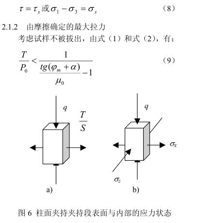
(2) There are three possible failures in the external tightening system: pull-out failure, surface failure and clamping internal yield failure. There are two possible failures in a self-tightening system: surface failure and clamping internal yield failure.
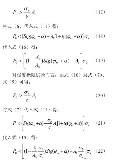
(3) In order to ensure that the specimen is not pulled out, P 0 is required for the external tightening system. Yield strength test requirement formula (17), ultimate strength test requirement formula (20). However, too much P 0 will produce surface failure and internal yield failure: if Eq. (18) is not satisfied, then the yield strength is usedSurface yielding occurs during testing; If Eq. (19) is not satisfied, then when the yield strength is testedYielding of the clamping section cross-section occurs. Similarly, if Eq. (21) is not satisfied, then surface yield will occur when the strength limit is tested; If Eq. (22) is not satisfied, the cross-sectional yield of the clamping section will occur during the strength limit test. It can be seen that the setting of the initial preload pressure P 0 of the fixture should not be too small and not too large. If it is too small, the initial preload of the specimen cannot be guaranteed, and if it is too large, it is easy to cause yield failure.
In practice, it is necessary to adjust the yield limit and size of the sample according to the material, so as not to cause yield failure.
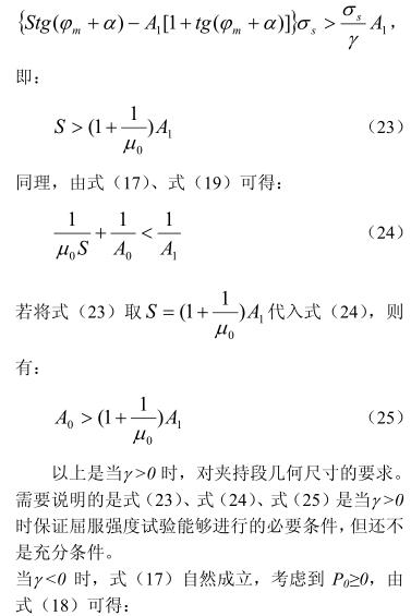
(4) The geometric dimensions of the specimen of the external tightening system need to be full
Conditions of the sufficiency: Eq. (23), Eq. (24), Eq. (25), Eq. (29), Eq. (30), Eq. (31).
(5) The self-tightening system theoretically does not require initial pressure, and P0 can be zero.
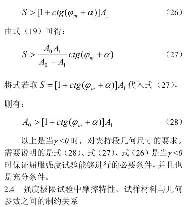
However, there are still conditions that need to be met for the geometric dimensions of the specimen: Equation (26), Equation (27), Equation (28), and Equation (32), Equation (33), Equation (34).
(6) Common types of failure
To investigate the mechanical conditions under which the test can be carried out normally, T and P0 need to satisfy Eq. (1), Eq. (4), Eq. (6), Eq. (7) or Eq. (9) and Eq. (11) and Eq. (15) at the same time. If one or more of these conditions are not met, a corresponding invalidation will occur. Failure types can also be classified by the satisfaction of these relationships. For example, if only equation (1) is not satisfied, and everything else is satisfied, elastic failure occurs, and the form of failure is unplugging. When equation (4) is not satisfied, the failure that occurs is the initial clamping failure. When Eq. (11) and Eq. (15) are not satisfied, and the others are satisfied, the failure at the jaw will occur when the yield strength test and ultimate strength test are carried out.
(7) The coefficient of friction between the specimen material and the clamp is μ0From Eq. (1), the greater the coefficient of friction μ0, the better.
(8) The contact area between the specimen and the clamp S
From the point of view of ensuring the effective clamping, the larger the contact area S, the better, and from the point of view of reducing the size of the specimen, the smaller the S, the better. For plate specimens, not only the contact area should be considered, but also the thickness of the specimen. For cylindrical specimens, the contact area S is calculated as the projected area. This is because the clamping positive pressure is not perpendicular to the circumferential direction of the cylindrical face.
(9) The geometric parameters of the clamp block α, friction and lubrication parameters φm are determined by equation (9), in order to ensure that the sample is not pulled out, the geometric parameters of the clamp block α, friction and lubrication parameters φm are smaller, but the geometric parameters α of equations (4), equations (11) and equations (15) should not be too small, and yield failure will occur if they are too small, and the adjustment range of the fixture to the sample diameter or sample thickness is also limited. For a testing machine, the geometrical parameters α determined by the manufacturer at the time of design. φm is related to the state of lubrication, and its value itself is small when designed. As long as the testing machine is properly maintained and lubricated, the specimen will not be pulled out.
3 Experience, Experimentation and Validation
In the above theoretical analysis results, the content related to the specimen and operation can be confirmed by the long-term experience of the experimental operator. It can also be verified through purposeful experiments. Experience occurs by chance when other tests are performed. Experiments for validation are deliberately arranged for validation.
3.1 Adjust the initial pressure test
Many testing machines are now equipped with clamping pressure adjustment systems that allow for adjustment of P0 forces. Usually, the samples that have been done are set empirically, and the new samples are determined by comparison on the one hand, and the preliminary test is explored and adjusted by using the preparatory specimens on the other hand. Despite a set of operating procedures and methods, it is still unavoidable that the specimen is pulled out and pinched flat when the clamping force is too small or too large.
In the verification test, a number of ordinary low-carbon steel specimens for material mechanics experiments are taken, and the initial test pressure of the 500KN testing machine is adjusted, and it will be flattened when it is maximum; It will be pulled out in the minimum test.
3.2 Change the clamping length test
The gripping length of the specimen is used as much as possible during operation. Do a verification test, and find that if the clamping force is not enough, it will be pulled out; The clamping force is too large and the clamping force is flattened. If the clamping length is too short, it will be pulled out even if the clamp is flattened.
3.3 Change the friction characteristics of the chuck
Under normal circumstances, as long as the clamping force is adjusted appropriately and the clamping length is appropriate, there will generally be no slippage between the chuck and the specimen during the tensile test. However, when carrying out the tensile test of the plate, because the plate is wider than the chuck, the required clamping force is larger, and the slippage phenomenon between the plate and the clamp block sometimes occurs, sometimes even if the chuck pressure has been adjusted to the maximum, there is no way, but sometimes a new pair of clamp blocks may be solved. This is because the coefficient of friction of the new clamp is large. When doing the verification test, use a set of new and old clamp blocks, the new one is installed on the upper chuck, and the old one is below, and you can see the slippage between the plate and the lower clamp block when loading.
3.4 Tensile test of equal coarse samples
The ultimate strength (breakage) test is carried out with plates, steel bars, steel wires, iron wires, and steel strands processed into samples of equal thickness. The results show that the specimens made of plates and steel bars can be tested for ultimate strength on ordinary fixtures, but occasionally they break at the jaws. Iron wires, steel wires, and steel strands are broken at the jaws when the ultimate strength test is carried out on ordinary fixtures. Properly protected iron wires can also be tested on ordinary fixtures or on occasional extreme strength tests. Steel wires and steel strands need to be tested on special fixtures to carry out ultimate strength tests, but they are not all successful.
On the one hand, the test results verify the theoretical analysis results: the contact area has an influence on the clamping; On the other hand, there is a contradiction between the test results and the theoretical analysis results: Eq. (25), Eq. (28), Eq. (31), and Eq. (34) show that for the tensile test to be carried out, the cross-sectional area A0 of the clamping section needs to be greater than the cross-sectional area A1 of the working section. The coarse specimen to be carried out (even individually) is A0 equal to A1.
4 Concluding remarks
Based on the model of the elastoplastic material, the influence of the initial clamping force, the geometric size of the specimen, and the friction characteristics of the specimen and the fixture on the clamping during the tensile test was analyzed, and the constraints between the factors affecting the specimen clamping were established. For the yield limit test and strength limit test, the conditions to ensure that the test can be carried out normally are found.
The theoretical analysis results are verified and verified by experience and experiments. The results show that the conclusions of the theoretical analysis are consistent with the actual test. However, in the tensile test of the equivalent coarse sample, there are facts that exceed the theoretical analysis results. This suggests that there are limitations to the analysis in this paper. This limitation is caused by the deterministic assumptions of the model, not a logical error, and the results of the analysis are still valid for the deterministic factor control phenomenon. The problem of tensile testing of isocoarse samples involves the random distribution of size and material properties, which cannot be explained by a deterministic material model, and needs to be analyzed by a random model considering materials. Stochastic analysis has also been completed and will be presented in a separate article.

