1. Overview
1.1 Scope of Application
HS160The tool series ultrasonic Thickness Gauge, using the ultrasonic measurement principle, is suitable for the measurement of the thickness of various materials that can make the ultrasonic waves propagate inside at a constant speed and can be reflected from their back.
Another important aspect of the instrument is the ability to accurately measure a wide range of plates and machined parts, as well as the monitoring of various pipes and pressure vessels in production equipment and their use
The degree of thinning after corrosion. It can be widely used in petroleum, chemical industry, metallurgy, shipbuilding, aviation, aerospace and other fields.
1.2 Rationale
The principle of ultrasonic thickness measurement is similar to that of light wave measurement. The ultrasonic pulses emitted by the probe reach the object to be measured and propagate through the object, and are reflected back to the probe when they reach the material interface, and the thickness of the measured material is determined by accurately measuring the time it takes for the ultrasonic waves to propagate through the material.
13. The basic configuration and the name of each part of the instrument
131 Basic Configuration:
Main unit: 1 set
L51 ordinary probe 1 pcs
Couplant 1 bottle
Instrument case: 1 pc
132 Options:
L77 microdiameter probe
LZ2 cast iron probe
Standard test blocks
1.3.3 Name of each part of the instrument (see figure)
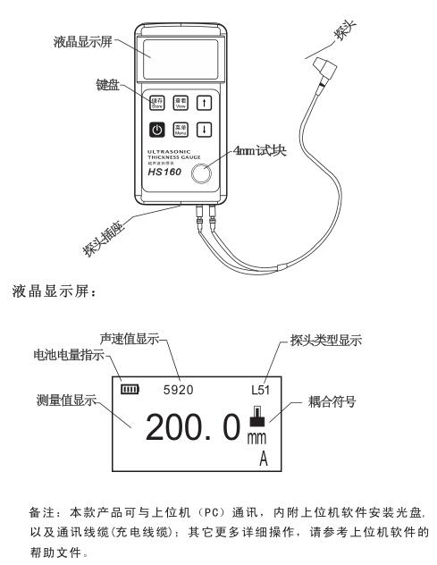
Keyboard function description:
Save --- Stores the currently measured values to a selected folder.
View --- read the measurement data already stored in the current folder.
↑ --- for adding numbers or menu selection; The backlight can be turned on and off under the test interface
↓ --- used for minus numbers or menu selection; Calibrate the instrument zero point under the test interface
Menu --- used to access the menu or confirm
◎--- used to turn on and off the menu; A long press can force the instrument to be reset
2. Performance indicators

Measuring range: 07mm~25000mm
Display resolution: 0.01mm or 0.1mm
Indication error: ±(1%H+0.06)mm
Lower Measurement Limit of Pipe (Steel): φ20mm×3.0mm (L51 probe)
φ15mm×2.0mm(L77 probe)
The indication error does not exceed ±0.06mm
Sound velocity adjustment range: 1000m/s~10000m/s
Measured sound velocity with known thickness: the measurement range is 1000m/s~10000m/s, and when the thickness of the test block is ≤20mm, the sound velocity measurement accuracy is ±1mm/h×100%; When the thickness of the test block is > 20mm, the sound velocity measurement accuracy is ±5%.
Ambient temperature: 0°C~40°C
Power supply: 1000mAh rechargeable lithium battery
Power consumption: working current< 50mA (without backlight) Dimensions: 133mm×66mm×25mm Weight: 245g

Note: If the coupling mark does not display or flashes, it means that the coupling is not good, and if the measurement thickness value runout, it means that the test hand is moving or the coupling is not good!!
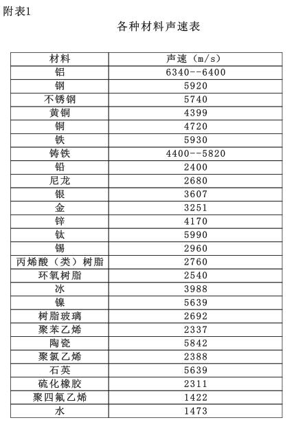
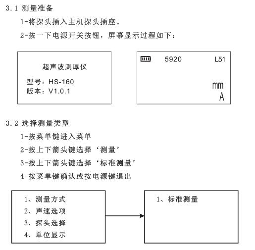
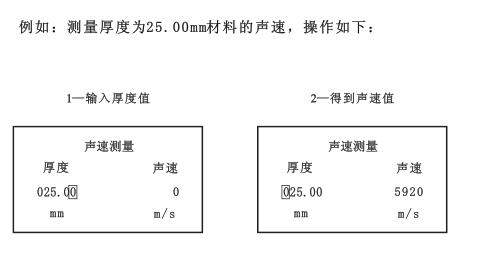
3.11 Measure the speed of sound
If you want to measure the sound velocity of a material, you can measure the sound velocity with a test block of known thickness. First, measure the test block with a vernier caliper or micrometer to accurately read the thickness value. Couple the probe with a known thickness block, select the velocity measurement interface, enter the thickness of the block, make sure the probe is not shaking and is well coupled, and then press the 'Menu' button, at which point the instrument displays the measured velocity of the measured object.
Sound velocity measurement requires the selection of a test block of sufficient thickness, with a recommended minimum wall thickness of 30 mm.
Note: Thickness values can be entered multiple times for measurement (retest)
3.12 Thickness value storage
If the measured value does not jump when taking a measurement, you can store the measured value and press the 'Save' button to store the current measured value in the current folder.
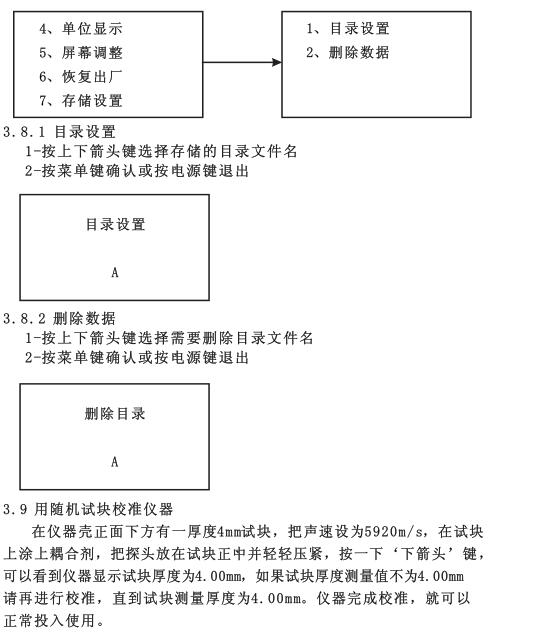
3.13 Deletion
You can clear the storage contents of the folder where the data is already stored in order to store other new measurement data, see 3.8.2 for the operation method
3.14 Backlight
Press the 'Up Arrow' button once on the measurement interface to turn on the backlight, and then press the 'Up Arrow' again
, the key backlight is off. If possible, do not turn on the backlight to conserve battery power.
3.15 Battery level indication
In the measurement interface, you can see the usage of battery power. When the battery level shows only a small black bar, please charge it immediately to avoid low power affecting the test result.
3.16 Shutdown
There are two ways to shut down, press the power button on the measurement interface, and the instrument will be powered off. If there is no operation within 3 minutes of the power-on state, the instrument will automatically shut down.
4. Measurement technology
4.1 Clean the surface
Before measuring, all dust, dirt and rust should be removed from the surface of the object to be measured, and the covering such as paint should be removed.
4.2 Improve roughness requirements
Excessively rough surface will cause measurement error, and even the instrument can not measure, the surface of the measured material should be smoothed as much as possible before measurement, and grinding, throwing, filing and other methods can be used to make it smooth. High-viscosity couplants can also be used.
4.3 Rough machined surface
In addition, adjust the angle between the transducer crosstalk separator plate (through the thin metal layer in the center of the bottom surface of the probe) and the fine groove of the measured material, so that the separator plate and the fine groove are perpendicular or parallel to each other, and the minimum value of the reading is taken as the measurement thickness, which can achieve better results.
4.4 Measure cylindrical surface
For the measurement of cylindrical materials, such as tubes, oil drums, etc., the importance of selecting the angle between the transverse barrier plate of the probe and the axis of the material to be measured cannot be overstated. To put it simply, the probe is coupled to the material to be measured, the probe crosstalk barrier plate is parallel or perpendicular to the axis of the material to be measured, and the probe is slowly and vertically shaken along the axis of the material to be measured, and the readings on the screen will vary regularly, selecting the minimum value in the reading as the accurate thickness of the material.
The standard for selecting the angle direction of the intersection of the probe crosstalk separator plate and the axis of the measured material depends on the curvature of the material, the pipe with a larger diameter, the probe crosstalk separator is perpendicular to the axis of the tube, and the pipe with a smaller diameter is selected to measure parallel and perpendicular to the axis of the tube, and the minimum value in the reading is taken as the thickness of the measurement.
4.5 Composite shape
When measuring a material with a composite profile (such as at the elbow of a pipe), the method described in 5.4 can be used, except that a secondary measurement is to be made, and two values of the transcultural diaphragm of the probe are read perpendicular to the axis and parallel to the axis, and the smaller number is used as the thickness of the material at the measurement point.
4.6 Non-parallel surfaces
In order to obtain a satisfactory ultrasonic response, the other surface of the material to be measured needs to be parallel or coaxial to the surface being measured, otherwise it will cause measurement errors or no readings at all.
4.7 Influence of temperature of materials
The thickness of the material and the ultrasonic propagation velocity are affected by the temperature, if the measurement accuracy is required to be high, the test block comparison method can be used, that is, the test block of the same material is measured under the same temperature conditions, and the temperature compensation coefficient is obtained, and the measured value of the workpiece is corrected with this coefficient.
4.8 Large attenuation materials
For some materials such as fibers, porous, and coarse particles, they can cause a large amount of scattering and energy attenuation of ultrasonic waves, resulting in abnormal readings or even no readings (usually abnormal readings are less than the actual thickness), in which case the material is not suitable for testing with this thickness gage.
4.9 Reference test blocks
Precise measurements are made of different materials under different conditions, and the closer the material of the calibration block is to the material being measured, the more accurate the measurement. A satisfactory reference block will be a set of test blocks of different thicknesses of the material to be measured, which will provide the instrument to compensate for the correction factors (e.g., microstructure of the material, heat treatment conditions, particle orientation, surface roughness, etc.). In order to meet the requirements for maximum accuracy measurements, a set of reference test blocks will be important.
In most cases, a satisfactory measurement can be obtained using only one reference block
Accuracy, this test block should have the same material and similar thickness as the material being measured. Take the uniform material to be measured with a micrometer and use it as a test block.
In the case of thin materials, when its thickness is close to the lower limit of probe measurement, a test block can be used
Accurate low limits. Do not measure materials below the lower limit thickness. If a thickness range can be estimated, then the upper limit of the thickness of the test block should be selected.
When the material to be measured is thick, especially the alloy with complex internal structure, it should be in a group
Select one of the test blocks that is close to the material to be measured for easy calibration.
The internal structure of most forgings and castings is directional, in different directions, its sound
There will be a slight variation in velocity, and in order to solve this problem, the test block should have an internal structure in the same direction as the material being measured, and the sound waves should propagate in the same direction as in the test material.
In a certain case, the function of checking the sound velocity of the material is known, so the sound velocity can be measured first, and then
The workpiece is measured at this speed of sound.
4.10 Several Methods in Measurement
1- Single measurement method: measurement at a point
2- Double measurement method: two measurements are made with the probe at one point, and the transverse sound partitions of the probe should be perpendicular to each other during the two measurements. The minimum value in the reading is selected as the exact thickness of the material.
3- Multi-point measurement method: multiple measurements are carried out within a certain measurement range, and the minimum value is taken as the material thickness value.
4.11 Probe Selection
See the relevant selection table!!
4.12 The wear of the crosstalk partition of the probe will affect the measurement, and the probe should be replaced when the following phenomena occur.
1- When measuring different thicknesses, their measurements always show a certain value.
2- Plug in the probe and do not take a measurement, there is a coupling mark or a measured value.
4.13 Casting measurement
Casting measurement has its peculiarities. The grains of the casting material are relatively coarse, and the structure is not tight enough.
In addition, measurements are often carried out in a rough state, so it is difficult to measure.
The first is the coarseness of the grains and the non-compactness of the structure that causes a great attenuation of sound energy, which is caused by the scattering and absorption of sound energy by the material. The degree of attenuation is closely related to the grain size and ultrasonic frequency, and the attenuation increases with the increase of grain diameter at the same frequency, but there is a highest point, beyond which the grain diameter increases again, and the attenuation basically tends to a fixed value. The attenuation for different frequencies increases with frequency.
Secondly, due to the coarse grain size and the presence of coarse out-of-phase structure in the casting, abnormal reflections, i.e., grass-like echoes or tree-like echoes, will cause false readings and misjudgments.
In addition, with the coarse size of the grains, the elastic anisotropy in the direction of the metal crystallization is more significant, so that the sound velocity in different directions can be different, and the maximum difference can even reach 5.5%.
In addition, the compactness of the tissues at different points within the workpiece is inconsistent, which also causes differences in sound velocity. These will result in inaccuracies in the measurements. Therefore, special care should be taken with the measurement of castings.
When measuring castings, you should pay attention to:
1. When measuring castings with unmachined surfaces, it is necessary to use engine oil with high viscosity. Butter and water glass are used as couplants.
2. It is better to use the same material as the DUT and measure the sound velocity of the calibration material of the standard test block with the same direction as the DUT.
5. Prevention methods for measurement errors
5.1 Ultra-thin materials
With any ultrasonic Thickness Gauge, the thickness of the material to be measured falls below the lower limit of probe use will result in measurement errors, and if necessary, the minimum limit thickness can be measured using the block comparison method.
When measuring ultra-thin materials, sometimes an error result called "double refraction" occurs, which results in the display reading being twice the actual thickness, and another error result is called "pulse envelope, cyclic jumping", which results in a measurement value greater than the actual thickness, and in order to prevent such errors, the measurement check should be repeated when measuring critical thin materials.
5.2 Rust spots, corrosion pits, etc
Rust spots and pits on the other surface of the material to be measured will cause irregular changes in readings, and in extreme cases, even no readings, and small rust spots are sometimes difficult to detect. When a pit is found or when doubts are made, this area needs to be measured with great care, and the probe can be positioned at different angles for multiple tests.
5.3 Material Identification Errors
When an instrument is calibrated with one material and then tested with another, the wrong results will occur, and care should be taken to select the correct sound velocity.
5.4 Wear and tear of the probe
The surface of the probe is made of acrylic resin, which will increase the roughness and reduce the sensitivity due to long-term use, and the user can use sandpaper or stone to smooth the surface of the probe with a small amount of sandpaper or stone to ensure the parallelism if the error is determined to cause error for this reason. If it is still unstable, the probe will need to be replaced.
5.5 laminated materials, composite materials
It is not possible to measure uncoupled laminated materials because ultrasound waves cannot penetrate uncoupled spaces. In addition, because ultrasonic waves cannot propagate at a uniform speed in composite materials, instruments that measure thickness by the principle of ultrasonic reflection are not suitable for measuring laminated materials and composite materials.
5.6 Effect of oxide layer on metal surface
Some metals can produce a dense oxide layer on its surface, such as aluminum, etc., this layer of oxide layer is tightly bonded with the matrix, and there is no obvious interface, but the propagation speed of ultrasonic waves in these two substances is different, so it will cause errors, and the thickness of the oxide layer is different, and the size of the error is also different.
5.7 Unusual thickness readings
The operator should be able to identify anomalous readings, which are usually caused by rust spots, corrosion pits, and internal defects in the material being measured. For solutions, refer to 5.2 and 5.3
5.8 Use and selection of couplant
The couplant is used as a high-frequency ultrasonic energy transfer between the probe and the material being measured. If the type is not selected or used incorrectly, there is a risk that there will be an error or the coupling mark will flicker and cannot be measured. The couplant should be used in moderation and evenly applied.
It is important to choose the right kind of couplant, and when working with smooth material surfaces, low-viscosity couplants (e.g., randomly configured couplants, light motor oils, etc.) are suitable. When used on rough surfaces, or on vertical surfaces and top surfaces, high viscous couplants (e.g. glycerin paste, butter, grease, etc.) can be used.
Couplant of various formulations are available in our company in various places.
6. Precautions
6.1 Cleaning of test blocks
Since the couplant is applied to the instrument using a random test block, it is necessary to take care to prevent rust. Wipe the random test block clean after use. When the temperature is high, do not get it in the Chinese liquid. If you do not use it for a long time, you should apply a small amount of grease to the surface of the random test block to prevent rust, and when you use it again, wipe the grease off and work normally.
6.2 Cleaning of the casing
Alcohol. The diluent has a corrosive effect on the casing (especially the window), so when cleaning, gently wipe it with a small amount of water.
6.3 Probe protection
The probe surface is acrylic and sensitive to rescratching of rough surfaces, so it should be gently pressed in use. When measuring rough surfaces, minimize the scratching of the probe on the working surface.
When measuring at room temperature, the surface of the analyte should not exceed 60°C, otherwise the probe can no longer be used.
Oil. The adhesion of dust will cause the probe cable to gradually age and break, and the dirt on the cable should be removed after use.
6.4 Maintenance of the battery
Charging should be carried out immediately after the low voltage indication is present, as follows:
A. Shutdown
B. Connect the random data cable with the instrument, then connect the charger and plug it into the mains socket;
C. The instrument will automatically turn on, enter the charging interface, and display the plug symbol when it is fully charged.
6.5 Strictly avoid collisions, moisture, etc.
7. Maintenance
7.1 When the error of the measured value is too large, please correct it.
7.2 If there are any of the following problems, please contact the manufacturer's maintenance department: A The instrument is damaged and cannot be measured
B. The display screen is not normal.
C. The error is too large during normal use.
D. Keyboard operation is out of order or confused.
7.3 Non-professional maintenance personnel cannot disassemble and repair by themselves.