Wet film thickness determination
Determining the range of dry film thickness for each coat inevitably requires controlling the wet film thickness of the coating. The correspondence between wet film thickness and dry film thickness is different with the coating variety and construction viscosity, even if it is the same type of variety, different color products, due to the different pigment base ratio and the different oil absorption of each color (filler), the correspondence between the wet film thickness and the dry film thickness is also very different, so the correspondence should be verified by the test in advance to find out the correspondence and then demonstrated. By measuring the thickness of the wet film, the thickness of the dry film can be roughly estimated to avoid excessive errors. However, the determination of the wet film thickness is inaccurate, and the coating thickness should ultimately be determined by measuring its dry film thickness.
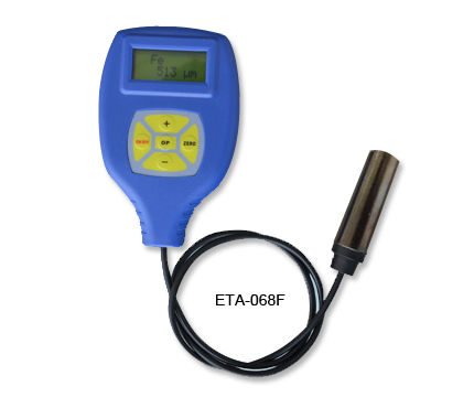
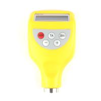
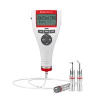
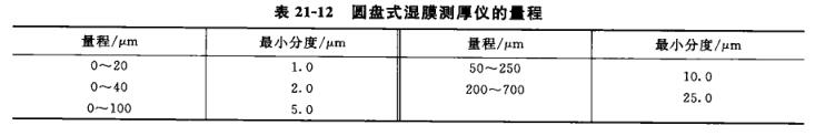
At present, the most common wet Film Thickness Gauge is disc-shaped (wheel gauge) and plate-shaped (comb gauge) two, its measuring principle is that there are three surfaces in the two surfaces of the same horizontal plane, when the outer two surfaces are pressed against the bottom plate below the wet film, its third surface is perpendicular to the wet film surface, because the third surface has a height difference with the outer two surfaces, in the measurement process, the point that the third surface first touches the wet film surface is the wet film thickness. The shape of the wet Film Thickness Gauge is shown in Figures 21-14 and 21-15.
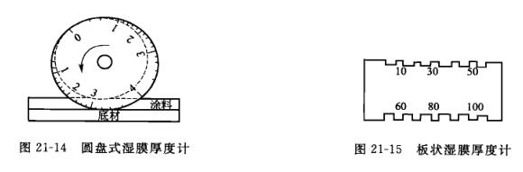
Disc wet Film Thickness Gauge can be divided into Table 21-12 according to its different ranges.
The measurement range of the domestic QVL type disc wet Film Thickness Gauge is 0~150μm, and the minimum index is 15μm.
The disc type wet Film Thickness Gauge consists of an eccentric wheel supported by two concentric wheels, on which a symmetrical scale is engraved, and the gap between the wet film and the eccentric wheel changes when the gauge is rolled on the paint film. The point where the paint film first touches the center wheel, and the scale on the eccentric wheel corresponding to this point is the thickness of the paint film at that point. When measuring, place the gauge on the wet film so that its minimum reading is at the top, with the maximum gap between the eccentric wheel and the paint film just above the wet film. Let the Thickness Gauge roll half a week in the direction of the minimum scale of the Thickness Gauge on the paint film, and repeat the roll in the opposite direction for half a circle, and read the readings of the contact point between the wet film and the eccentric wheel when rolling in both directions, and the average value is the test result. It should be noted that the instrument needs to be perpendicular to the surface to be measured when used, otherwise the correct result will not be obtained; In addition, the rolling of the instrument on the surface, if it starts from zero, the test results will also have a certain error due to the squeezing of the coating film, the same principle, the external teeth of the plate type wet Film Thickness Gauge are on a baseline, and the internal teeth are successively shortened, so that a series of gaps appear between the teeth and the baseline, and the height of each gap can be read by the scale on the instrument. When measuring, it is placed firmly on the substrate by placing the tooth on the wet film surface normally, removing the instrument, and the maximum reading of the wet film adhesion to the inner tooth is the wet film thickness. Because the thickness of each tooth type is expressed with a certain spacing, the test error is larger than that of the disc type wet Film Thickness Gauge.
Whether you are using a disc type wet Film Thickness Gauge or a plate type Thickness Gauge, the test should be carried out as soon as possible after painting to avoid large measurement errors caused by solvent volatilization and thinning of the wet film.
Determination of dry film thickness
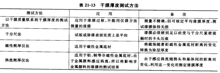
The national standard analysis methods are: GB/T1764-79 "Paint Film Thickness Determination Method"; GB/T13452.2-92 "Determination of the thickness of the coating film of basecoat and varnish". The practical analysis methods of the factory are: lever dry scale method, magnetic Thickness Gauge method. Microscopes, penetration Thickness Gauges, etc. can also be used to test the thickness of the dry film. The methods and instruments used to determine the thickness of the dry film vary according to the type of substrate and the nature of the paint film, and the following methods can generally be used, as shown in Table 21-13.
The choice of test site will affect the test results, and when using a magnetic Thickness Gauge, the test results are inaccurate if measurements are taken too close to the edge or inside corner of the test face because the instrument is sensitive to sudden changes in the surface of the test sample. This phenomenon is called the edge effect, and the influence range of the edge effect depends on the test method and instrument, and the distance from the uneven place is generally 3~13mm. Even if the thickness of the paint film on the surface of the test board is tested with a dry minute scale, the thickness of the paint film at the edge of the test board is different from the thickness of the paint film at the center of the test board due to various reasons, and it cannot be tested close to the edge. The selection of the test site is related to the size, shape and requirements of the coating quality of the test surface, for example, the selection of the measurement part on the 150mmX100mm test board is shown in Figure 21-16, and the commonly used dry film thickness test methods are as follows.
(1) Dry scale method
 Measured with a lever dry minute scale with an accuracy of 2 μm, the paint film needs to be hard enough to withstand the indentation of the chuck head when the dry minute is in close contact. This method is only suitable for sheet test surface or similar flat surface, the first professional dry minute ruler "0" position calibration, wipe the two measuring surfaces with silk cloth, rotate the differential cylinder, so that the two measuring surfaces are gently in contact with each other, when the pointer coincides with the dial "O" line, stop rotating the differential cylinder, then the "O" line on the differential cylinder should also coincide with the axial engraved line on the fixed sleeve, the edge of the differential cylinder and the left edge of the "O" line of the fixed sleeve are exactly tangential, so that the "0" position is correct. If the "O" position is not accurate, it must be adjusted so that the pointer coincides with the "0" line of the dial, fix the movable measuring rod with a stopper, loosen the back cover, and then adjust the "O" line on the differential to coincide with the axial engraving line on the fixed sleeve, the edge of the differential cylinder is exactly tangent to the left edge of the "O" line of the fixed sleeve, and then tighten the back cover, release the stopper, and see if the dial pointer is correct to the "O", if not, repeat the above steps and re-zero.
After determining the test site of the measuring surface, first place the unpainted bottom plate between the micro motion measuring rod and the movable measuring rod, slowly rotate the differential simplification, so that the pointer is between the two tolerance zone pointers, and then adjust a certain line on the differential cylinder to coincide with the axial engraving line on the fixed sleeve, in order to eliminate the measurement error, you can measure several times in the original place, when reading, add up the numbers read on the fixed sleeve, the differential simple and the dial, that is, the measured thickness value, and then apply the paint sample, dry it at the specified time, and then measure it at the same position according to this method, The difference between the two is the thickness of the paint film.
If it is to measure the thickness of the paint film that has been painted, a circle with a diameter of about 1omm should be gently drawn on the test part that has been determined in advance, and an obvious number should be added next to it, and the thickness of the paint film should be measured according to the above method, and the thickness of the paint film of each part should be recorded, and then the paint film of each test part should be removed with an appropriate solvent or paint remover, and then the thickness of the substrate should be measured, and the difference between the two is the thickness of the paint film. At least 5 positions at least 1 cm away from the edge should be taken upper, middle and lower.
After the measurement, the arithmetic average of the paint film thickness of each test part is calculated, and the result is the average thickness value of the paint film.
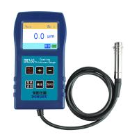
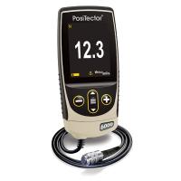
(2) Magnetic Thickness Gauge method
With an accuracy of 1 μm, it is a non-destructive measurement method of dry film thickness on metal substrates and can be used on magnetic metal substrates. The magnetic method is used to determine the coating thickness by the linear change of the magnetic flux or mutual inductance current of the probe on the magnetic substrate, and this method is only suitable for measuring non-magnetic coatings on the surface of magnetic substrates. According to the measurement principle, the test instrument is divided into two types: permanent magnet Thickness Gauge and electromagnetic Thickness Gauge. At least 5 positions at the top, middle and bottom of the sample edge are not less than 1cm away from the edge of the sample for measurement, and the average value is taken.
(1) Electromagnet This kind of instrument requires the supply of electricity, and is equipped with a device that supplies the electromagnetic head to stabilize the current. The head should be placed on an unpainted metal surface similar to the metal substrate under the test film to take the reading. The reading is then repeated on the painted surface. After the scale on the instrument is calibrated, the thickness of the paint film can be known by the difference between the two readings, (2) long-term magnet The instrument has a single-pole or multi-pole long-term magnet placed on the coating surface in a spherical contact state, and the contact is placed on the unpainted substrate with similar properties to the test plate, and the reading of the standard plate is adjusted to zero. The calibration of the instrument is usually performed with a non-magnetic gasket of known thickness supplied by the instrument, which is placed on a reference substrate and the reading is adjusted by means of a control knob to achieve the thickness of the standard film. After calibration, place the instrument on the painted surface and pay attention to the readings on the dial, to avoid any magnetism on the substrate, rotate the instrument 18o° and take a second reading on the same part of the membrane, if the second reading is different from the first, take an average and take several readings in the same way to obtain a representative result on the full range of the painted object.
(3) Magnetic attraction detachment instrument: This kind of instrument measures the thickness of the paint film by overcoming the force required by the magnetic attraction between the long-term magnet and the magnetic substrate. This gravitational force varies with the thickness of the non-magnetic paint film between the magnet and the substrate and is measured by the force exerted by the coil tension attached to the magnet for a long time. A variety of instruments can be used, including simple pencil-shaped spring scales and other types, where the applied tension is by rotating a corrected circular dial until the magnet separates from the painted surface.
Note: The instrument magnets should not be placed less than 25mm from any side of the test piece or where the magnetic field strength of the instrument will be uneven. These instruments should be frequently calibrated with a standard piece and a reference surface to confirm that the calibration is still valid.
Alternatively, the wafer can be placed on the test surface for verification to check whether the corresponding increase in readings from the known gasket thickness is within the accuracy limits claimed by the instrument.
Specimens are easily magnetized during mechanical handling and processing, which will affect the accuracy of the readings obtained. For this reason, the control specimen, which serves as a reference surface, should be as similar as possible to the specimen in terms of composition and handling prior to measurement.
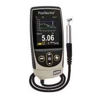
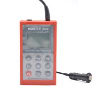
(3) Eddy current Thickness Gauge method
The operating principle of this type of instrument is that the apparent impedance of the probe coil changes due to the eddy current induced by the alternating magnetic flux of the coil in the non-magnetic metal surface of the test object. This, in turn, changes the amplitude of the alternating current flowing through the probe coil, which can be measured by the sensitivity meter to which the probe is attached. The magnitude of the induced eddy current varies with the distance between the probe coil and the base metal, i.e., the thickness of the dry paint film with which the coil is placed.
Due to the induction of eddy currents by metal pigments, the eddy current Thickness Gauge will have a certain impact on the test results when testing the thickness of the paint film containing some metal pigments such as aluminum powder and zinc powder, according to the different power sources used, the eddy current Thickness Gauge can be divided into two types, one needs to be supplied by alternating current, the other is a semiconductor type, powered by its own battery, the latter type is small and lightweight, easy to carry, both types require careful adjustment of the zero position on the control surface similar to the test object, It is then calibrated with a gasket of the characteristic plastic foil supplied with the instrument, and for the semiconductor type, after the main body is zeroed, there is usually no need for calibration, and the instrument probe is placed on the part to be tested, and the thickness value can be read after the indication is stabilized.
Recently, some digital display Thickness Gauges have been introduced with more intuitive readings, smaller sizes, and lighter sizes, but the same measurement steps as pointer Thickness Gauges often require several stages of zeroing, calibration, and then testing readings.
(4) In electrophoretic coating, the relationship between voltage and film thickness is measured
 By changing the voltage for electrophoresis coating, measuring the film thickness, making a voltage/film thickness relationship curve, and obtaining a satisfactory corresponding voltage, test instruments and materials: a set of electrophoresis coating device (including electrophoresis tank, rectifier, Drying Oven, etc., the same below); The phosphate board of the same material as the product on the production line, the specification is 70mmX150mmX0.8mm,
Steps:
(1) Select a few voltages in advance;
(2) Under the selected voltage, electrophoretic coating and drying are carried out according to the process parameters specified in the electrophoretic coating to be measured;
(3) After drying, the film thickness of each test plate is measured, and the following voltage/film thickness relationship curve is made (as shown in Figure 21-17).
The corresponding voltage with a better film thickness is obtained from the obtained voltage/film thickness relationship curve, Note: When measuring the voltage/film thickness, the difference in the data will occur due to the difference in the coating temperature, the agitation speed of the coating, and the area ratio of the anode and cathode. The above parameters should be specified according to the requirements of the coating to be tested.