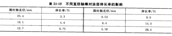
The flexibility of the coating is measured by bending the painted sample on shafts of different diameters, and it is expressed by the diameter of the small shaft that does not cause damage to the paint film after bending. Under the condition that the paint film is not damaged, the smaller the diameter of the bent mandrel, the better the flexibility of the coating. Because on shafts with different diameters, after bending the coating sample around the shaft, the elongation of the coating increases as the diameter of the shaft decreases. For example, a cold-rolled steel plate with a thickness of 0.787mm is coated with a 25µm thick coating and bent around the cylindrical axis for about 18o°, and its elongation is shown in Table 21-15.
When the coating is turned around the shaft, it is not simply to test the elasticity of the coating, but to reflect some comprehensive properties of the coating, such as tensile strength, tensile strength, adhesion between the coating and the bottom surface, etc., but generally referred to as Determination of flexibility.
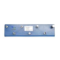
To measure the flexibility of the coating, a flexibility Tester can be used, as shown in Figure 21-26, which is composed of 7 steel shafts with different thicknesses, fixed on the base, and the base can be fixed on the edge of the test bench with screws.
The length of each shaft is 35mm, and the diameter and radius of curvature are different. After the flexibility Tester is assembled, the tolerance value of the perpendicularity of each shaft to the installation plane is not greater than 0.1mm.
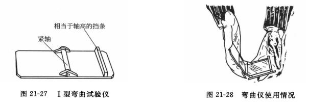
 When measuring, after the coating on the 25mmX120mmX(0.2~0.3)mm tinplate (tin-plated iron) plate is dry, under the condition of constant temperature and humidity, with the coating facing up, press the sample tightly on the shaft with both hands Bending around the shaft, after bending, the thumbs of both hands should be symmetrical to the center line of the shaft rod. The bending action must be completed within 2~3s, and then observe with a 4 times magnifying glass to see if there are any damage phenomena such as reticulation, cracks and peeling. If there is no above-mentioned phenomenon on the shaft rod, then twice the radius of curvature is the flexibility of the coating, expressed in mm. The flexibility of the coating can also be measured on a bending Tester (that is, a cylindrical shaft bending test), see Figures 21-27. The bending Tester can be divided into type I and type II according to the different measurement objects.
Type I bending Tester is suitable for test plates with a thickness of less than 0.3mm. It has a fixed hinge and connects the shafts of the cylinders. The diameters of the shafts are 2mm, 3mm, 4mm, 5mm, 6mm, 8mm, 10mm, and 12mm. , 16mm, 20mm, 25mm and 32mm. The gap between the shaft surface and the hinge seat plate is (o.55±o.o5)mm. When measuring, open the instrument completely, install a suitable shaft, insert it into the test plate, and make the painted surface face the seat plate, and then it can be bent. The operation should be within 1~2s, and the instrument should be closed smoothly rather than suddenly. , so that the test plate rotates 18o° on the axis. Then, immediately use normal vision or a 10x magnifying glass to check whether the coating is cracked or peeled off from the bottom plate (the coating less than 10mm away from the edge of the plate is not recorded).
Type II bending Tester is suitable for soft metals with a thickness not greater than 1.omm, such as aluminum plates, etc., and thicker plates can also be used on the premise of not distorting the shaft. The instrument is equipped with a series of cylindrical shafts of 6mm, 1omm and 13mm, which can be replaced as required, see Figure 21-28. When testing, install the instrument firmly on one end of the workbench and install a suitable shaft. Lower the handle to the vertical position, and place the test panel, painted side down, between the shaft and the bend. And make the test plate protrude about 40mm from the center line of the shaft to the bending direction during measurement, lock the nut and splint, so that the test plate is firmly clamped on the plate support. Insert the wedge into its ll1] slot and raise the plate support until the test plate just hits the shaft. Adjust the screw so that the bending piece rises to just touch the test plate, and within 1~2s the handle is raised 18o° steadily rather than suddenly, and the plate on the shaft is also bent 18o° at this time. In order to prevent damage to the coating during the bending operation, a thin piece of paper can be inserted on the coated surface between the plate support and the bending piece. After bending, remove the wedge and loosen the locking screw to lower the plate support and make the bend The test panel is removed from the shaft. Use normal eyesight or a 10 times magnifying glass to check whether the coating is cracked or peeled off from the bottom plate (the coating less than 10mm away from the edge of the plate is not recorded).
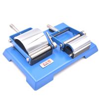
There is also a conical bending Tester for measuring the flexibility of the coating. The central axis is a cone with a length of 200mm and a diameter extending from a maximum of 38mm to a minimum of 3mm. After inserting and fixing the test plate, turn the upper handle so that the handle is deflected close to the surface of the cone to observe the minimum diameter that causes coating damage, which represents the flexibility of the coating.