 The adhesion of the coating depends on the adhesion between the coating and the surface of the coated object and the quality of the coating application, especially the quality of the surface treatment.
In addition, the influence of different substrates on the adhesion of the coating is also very obvious, generally speaking, the adhesion of the coating on steel is better than the adhesion on aluminum alloy, stainless steel and galvanized workpieces, so the latter should pay special attention to the selection of primer in the design of the coating system.
The national standard analysis methods are: GB/T1720-79 "Paint Film Adhesion Determination Method", GB/T9286-1998 "Scratch Test of Pigment and Varnish Paint Film", GB/T5210-85 "Coating Adhesion Determination Method", and the practical factory has the circle method, the grid method, etc.
Circle method
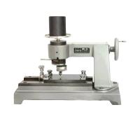
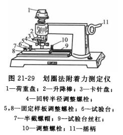
An adhesion Tester is used, as shown in Figure 21-29. Use the stylus as the needle and place the sample coating upwards. It is fixed on the test platform of the instrument, so that the tip of the stylus touches the coating, and the crank is rotated clockwise by hand, and the needle tip is drawn on the coating with a certain diameter circle at a uniform speed through the rotation mechanism. If the scratches do not reveal the bottom plate, add weights until the scratches expose the bottom plate, and the circles drawn are overlapped in turn to obtain a figure similar to a round rolling line, and then take out the sample, remove the paint chips on the scratches with a paint brush, and check and grade them with a four-fold magnifying glass.
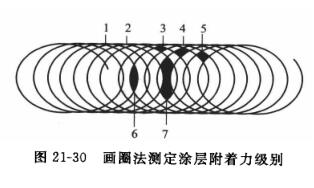 The adhesion of the circle method is divided into seven grades, see Figure 21-30, and the integrity of the coating of each part is checked in order, if more than 70% of the lattice of a certain part is intact, it should be regarded as intact, otherwise it should be determined as damaged. For example, if the coating of part 1 is intact, the adhesion is very good, and it is rated as grade 1; The coating of part 2 is damaged and part 2 is intact, and the adhesion is second, which is determined as grade 2. By analogy, grade 7 has the worst adhesion, and the coating is almost completely peeled off. The result is based on the same level of at least two templates.
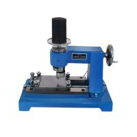
At present, there is a kind of electric adhesion Tester has come out, which is to add a motor to the hand-cranked Tester to drive the rotation mechanism, which avoids the disadvantages of uneven force and uneven speed of the hand-cranked Tester, and reduces the operation error. However, whether it is a hand-cranked or electric type, the stylus should have a radius of 5.25 mm and should be replaced at any time after wear, otherwise the test results will be affected.
Gridded
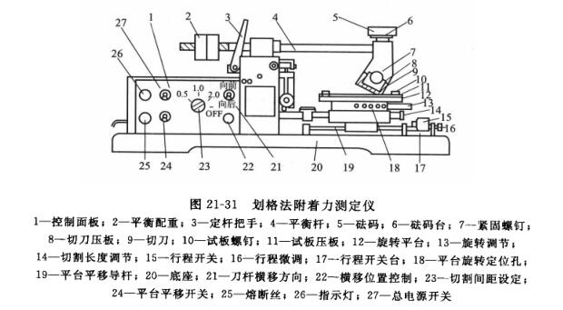
It is a manual or mechanical cutting method using a cutting tool to cut the coating according to the grid pattern, and the cutting should run through the coating to the surface of the substrate, and then evaluate the damage of the coating, as shown in Figure 21-31.
When cutting, first cut 6 or 11 parallel to each other on the coating of the test piece, with equal spacing (can be 1mm or 2mm), and then vertically cut the same number of cutting lanes and distance as the former, the number and spacing of the cutting line should be determined according to the nature of the coating and consultation with the relevant parties. When using manual cutting, the force should be uniform, and the speed should be stable and non-frequent. When cutting mechanically, a weight of appropriate weight should be added to the upper part of the knife so that the cutting edge can penetrate the coating and touch the substrate during cutting.
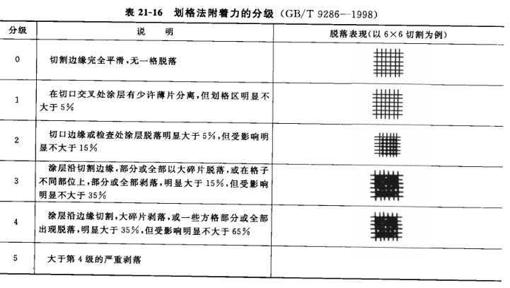
After cutting, 25 or 100 squares will appear on the board, and the chips will be gently brushed off with a soft-bristled brush along the two diagonal sides of the squares, and then the adhesion of the coating will be checked and evaluated.Table 21-16 shows a breakdown of the evaluation into six levels, the first three of which generally meet the general purpose and at which the results of the test can be expressed as "pass" or "fail".
 Tape method
 Tape method
In this case, the adhesive tape is applied to the incision of the coating, and the adhesion of the coating is evaluated by observing the adhesion of the coating after peeling off the tape.
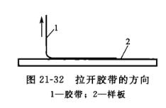
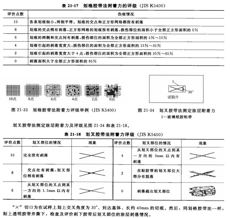
The adhesive tape method for determining coating adhesion is usually divided into two types according to the form of the incision: orthogonal incision and "X" incision. The orthogonal incision is the same as the above-mentioned drawing method, that is, 25 or 100 squares are drawn on the sample that penetrate the coating to reach the substrate, and then paste the transparent tape with a width of 18mm or 24mm and a sticking force greater than 2.94N per 10mm, the paste length is about 50mm, and the tape is completely attached to the coating with an eraser, and after 1~2min, one end of the hand-held tape is perpendicular to the coating surface and quickly (do not pull suddenly) to tear off the tape, as shown in Figure 21-32, Check the separation of coatings from the substrate or from the previous coating, and if there is separation between coats, the adhesion of the coating system to the substrate cannot be evaluated, but the layer from which it is separated should be documented. Adhesion evaluation methods are described in:Table 21-17 and Figure 21-33 are shown.
Pull the method
The adhesion determined by the pull-up method refers to the force required to apply a vertical and uniform tensile force on the cemented surface of the specimen at a specified speed, and the force required for adhesion failure between coatings or between coatings and substrates. Expressed in N/cm2 (kgf/cm2).
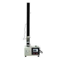
The equipment used in the pulling method to determine the adhesion of the coating is a Tensile Testing Machine, and the load selection of the Tensile Testing Machine should be suitable for the failure load of the sample. The fixtures used in the test should be able to align and fix the specimen. The testing machine should allow the tensile force to increase smoothly and act perpendicular to the surface of the test column. Its auxiliary devices are test columns and centering devices made of metals (steel, iron, aluminum, etc.). The diameter of the test column should be 2omm, the height should not be less than half of its own diameter, and its plane should be perpendicular to the long axis of the test column, as shown in Figure 21-35. The centering device is used to ensure the fixed coaxial arrangement of the specimen, as shown in Figure 21-36 (example of a centering device for a 20mm diameter test column).
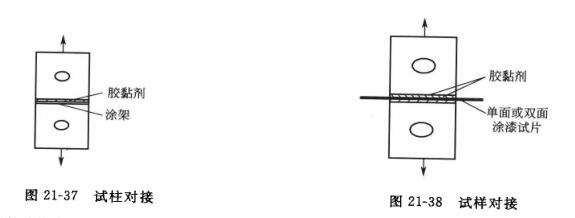
For testing, the paint is applied to a metal test column with the same material and surface finish as the practical substrate, and then cemented with an adhesive to another test column. The composition and shape are shown in Figure 21-37. Alternatively, the painted specimen is bonded to two clean column surfaces, as shown in Figure 21-38. The centering device is used to make the upper and lower test columns concentricly docked, and the adhesive should always remain motionless during the curing period, and after curing, use a sharp knife to cut through the domestic adhesive and coating along the perimeter of the test column to the substrate.
Put the prepared test column or sample into the upper and lower grips of the tensile machine, and adjust to the center, so that the cross-section can be evenly tensioned, and the fixtures are pulled apart at a tensile speed of 10mm/min until they are broken. Write down the load value of the specimen pulling apart and observe the failure mode of the section. The forms of destruction can be divided into the following types.
(1) The damage between the interface between the adhesion failure coating and the substrate and composite coating is represented by A.
(2) The cohesive failure coating itself is denoted by B.
(3) The adhesive itself is damaged or the topcoat is partially broken, which indicates that the adhesion between the coating and the substrate or the interfacial adhesion between the coating is greater than the obtained value, which is represented by C.
(4) Bonding failure: The adhesive is disconnected from the unpainted test column, or completely disconnected from the topcoat of the tested coating, which is represented by D.
When the failure mode is A, B or C, the measurement results meet the requirements of the adhesion test. If there are two or more forms of failure, the percentage of the damage area should be indicated, and more than 70% is effective. When D occurs, the selection, process and quality of the adhesive should be inspected or replaced. If C appears, it means that the strength of the adhesive cannot meet the requirements, and the material with higher adhesive strength can be replaced to quantitatively measure the adhesion of the coating.
Coating adhesion is calculated as follows:
F=G/S
The adhesion of F-coating in the formula, N/cm2;
G-load value when the sample is pulled away and destroyed, N;
Cross-sectional area of the S test column, cm2.
The test results are expressed in the form of adhesion and failure.
In addition, the scratch method can be used to test the adhesion of the coating, the main principle of which is to place the scraper (which can be a rounded stylus or ring) on the painted test plate, gradually increase the load on the scraper until the coating comes off the surface of the substrate, and determine the adhesion of the coating by the size of the load.
For the electrophoretic paint film, it is reported that the production can be soaked in ordinary tap water for testing, according to the set time, peel off with nails, with good adhesion, nails will not peel off the paint, generally immersed in water for 24h without peeling off the film layer can also be soaked in 5% NaOH, 5% H2S04 for 24h without peeling, salt spray test, artificial sweat test can also be up to standard.