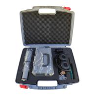
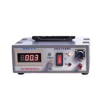
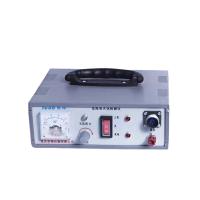
What is a leak?
When applying anti-corrosion coatings to metal substrates or applying waterproofing layers on concrete, holes, pinholes, or pores in the coating—known in the industry as "holidays"—are defects that must be discovered and repaired during construction and inspection. Leaks refer to discontinuities where the substrate is exposed or insufficiently protected; overly thin coatings, surface contamination, or air entrapment during construction can all be caused. Even the smallest defects can allow moisture, oxygen, and contaminants to reach the substrate, causing corrosion. Under harsh conditions such as immersion, chemical exposure, marine environments, and pipelines, undetected leaks can lead to rapid localized corrosion and premature coating failure.
How does a leak detector work?
The spark leak detector operates by moving a charged electrode across the coating surface. When a leak point is detected, current passes through the holes and enters the conductive substrate; the instrument detects the current and triggers an alarm.
Low-pressure wet sponge leak detectors are suitable for thin coatings (generally not exceeding 500 μm), forming conductive paths through wet sponge, with resistance thresholds usually of 80 or 90 kΩ. High-voltage spark leak detectors are suitable for thick coatings and do not use conductive media; sufficient voltage must be applied to break down air gaps. The thicker the coating, the higher the required voltage.
What happens if you choose the wrong voltage?
When the voltage is too low, the current cannot stabilize the arc to the substrate, and leaks will be missed. When the voltage is too high, it exceeds the dielectric strength of the coating, breaking through intact areas, creating new leaks, and damaging the coating.
The problem with the old method
In the past, the industry often used the rule of thumb of thumb of "100 volts per mil" (about 4 V/μm), or refer to voltmeters in various standards. However, these recommendations vary widely, are sometimes contradictory, and are based on historical experience rather than scientific models. Due to concerns about burn-through coatings, old recommendations are generally lower. In fact, many protective coatings have dielectric strengths exceeding 500 V/mil (about 20 V/μm), and the fusion of epoxy powder even exceeds 1,000 V/mil (about 40 V/μm), far exceeding the revised test voltage.
The basis for the new method
Controlled experiments by Walker and colleagues found that reliable leak detection requires higher voltages than traditional ones. The experimental data align with Paschen's Law, which refers to the relationship between the voltage required to generate an arc in air and the gap distance:
Metric (micrometers): V = 170 + 2.48d + 58√d
Imperial (mil): V = 170 + 63d + 293√d
Where V is the required voltage (volts), and d is the gap distance. Experiments show that the old recommendation is significantly lower for coatings thinner than 50 mils (1,250 μm).
The updated calculation formula
To cope with site conditions, add a margin to the theoretical minimum—multiply by 1.5 and add a 1,500 V baseline:
Metric (micrometers): V = 1,500 + 1.5 × (170 + 2.48d + 58√d)
Imperial (mil): V = 1,500 + 1.5 × (170 + 63d + 293√d)
Of this, 1.5 is the allowance for surface roughness, debris, and electrode condition, while 1,500 V is used to overcome the tiny gap between the electrode and the surface. This formula has been incorporated into ASTM G62-23, NACE SP0188-2024, ASTM D5162-24, ASTM D4787-24, and ISO 29601:2026.
Comparison of new and old voltages
For example, for a 635 μm (25 mil) coating, the new formula calculates about 6,300 V, while the old "100 V/mil" rule only recommends 2,500 V, the old NACE SP0188 recommends 3,000 V, and the old ISO 29601 recommends 3,500 V. For a 1,000 μm (40 mil) coating, the new formula is about 8,200 V, while the old linear law only about 4,000 V. The new formula for 50 mils (1,270 μm) coatings is 9.6 kV, while the old method uses 5.0 kV, 4.0 kV, and 7.0 kV, respectively. The new formula for 100 mils (2,540 μm) coatings is 15.6 kV, while the old method uses 10.0 kV, 10.0 kV, and 14.5 kV respectively. It can be seen that the difference is most pronounced in thin coatings, where the old recommendation is far below the voltage required for reliable defect detection.
Practical Recommendations
Confirm applicable specifications and standard versions.
Confirm the coating is fully cured and obtain the maximum test voltage allowed by the manufacturer.
Measure the actual thickness of the dry film and select representative thicknesses according to standard requirements; When thickness varies greatly, different voltages are set in each zone.
Calculate voltage or refer to current standard tables.
Confirm that the leak detector is properly grounded.
Verify the electrode voltage under load in the leak-free area, then verify the operation using known leak points or a comparison board.
Revalidate before and after use, after replacing electrodes or testing settings.
PosiTest HHD and PosiTest HHD C come with built-in voltage calculators for the above standards, simplifying setup and reducing manual calculation errors. When testing on concrete, conductive circuits must also be established according to ASTM D4787, considering the effects of concrete moisture, reinforcement, and conductive base coatings.
Summary
The revised voltage settings are based on the physical principles of air-electrical breakdown and controlled experiments, used according to standards and manufacturer limits, which can improve leak detection rates while reducing the risk of coating damage.