The structure of the instrument
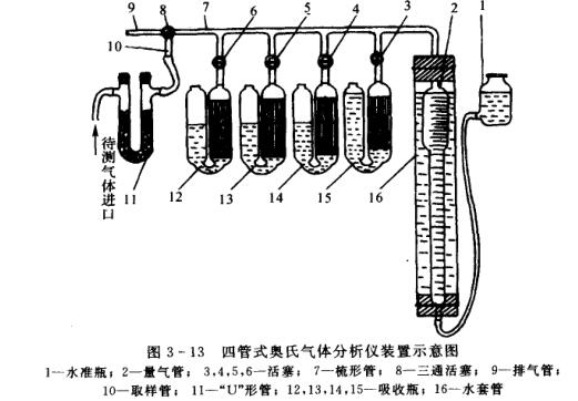
A commonly used Gas Analyzer is a four-tube Austenitic (0rsat) Gas Analyzer. The apparatus of the instrument is shown in Fig. 3-13, and its main components are gas measuring tube 2, leveling bottle 1 and 4 absorption bottles 12, 13, 14, 15. The whole set of instruments is packed in a portable wooden box.
The measuring trachea 2 is a relatively enlarged upper part and a slender glass tube at the lower part. The volume of the enlarged part is 50cm3, and a marking line (called zero line) is engraved on the upper part of the tube; each scale of the elongated part is equivalent to 0.1cm3 or 0.2cm3, and the scale value at the bottom is 100cm3. The burette 2 is installed in the water jacket 16 to reduce the change of gas temperature during analysis (why does the temperature change?). The level bottle 1 is a glass bottle with a side tube, which is connected to the lower end of the gas measuring tube 2 by means of a rubber tube, and a sealing liquid (acidic solution of saturated NaCl) is housed in the level bottle 1 and the gas measuring tube 2 .
The comb-shaped tube 7 communicating with the upper part of the measuring gas tube 2 is a thick-walled and slender glass tube, with four branch tubes with pistons 3, 4, 5, and 6 in the middle, and a three-way piston at the left end of the comb-shaped tube 8. The absorption bottles 12, 13, 14, and 15 are all composed of a thin curved glass tube connected to two enlarged glass bottles in the middle. The small tube on the top of one of the bottles has a marking line engraved on it. 7 branch pipes are connected. Some absorption bottles are equipped with some glass thin tubes to increase the contact surface between the absorption liquid and the gas to be measured. The absorption liquid can be added from the mouth of another glass bottle; the upper end of the bottle is usually closed with a stopper or a rubber tube with a clip (to prevent the absorption liquid from contacting with 02, C02, etc. in the air and cause premature failure) ;Only turned on when in use.
Rotate the three-way piston 8 at the left end of the comb-shaped tube 7, so that the instrument (through the sampling tube 10 and the "U"-shaped tube 11) communicates with the gas to be measured, or communicates with the outside atmosphere through the exhaust tube 9, or isolates it from the outside world. .
When sampling, the sampling tube 10 is connected to the "U"-shaped tube 11 with a rubber tube 11, and the other end of the "u"-shaped tube 11 is connected with the pipeline of the gas container to be tested. The "U"-shaped tube 11 needs to be filled with some cotton or glass fiber to filter solid impurities such as smoke and dust mixed in the gas sample to be tested.
Instrument use
For example, four-tube Austenitic (0rsat) Gas Analyzer is used for flue gas analysis. The main components of flue gas are gases such as C02,, CO,, O2 and N2.
1. Preparation before analysis
(1) The installation of the instrument. Clean the Gas Analyzer, dry each glass piston carefully with filter paper, and then apply a thin layer of lubricating grease evenly, and be careful not to let the lubricating grease enter the piston hole. Then assemble according to Figure 3-13. Fill the absorption bottle with the required absorption liquid respectively, so that the volume of the solution reaches half of the volume of the absorption bottle.
The absorption bottle 15 is filled with potassium hydroxide solution; the absorption bottle 14 is filled with pyrogallic acid-potassium hydroxide solution; the absorption bottle 13 is filled with cuprous chloride-ammonia solution; the absorption bottle 12 is filled with sulfuric acid solution; Fill level bottle sealing solution in level bottle 1; Be full of water in water sleeve pipe 16
(2) Check the air tightness of the instrument. Turn the three-way piston 8 to the position connected to the atmosphere, raise the level bottle, and make the sealing liquid fill the gas measuring tube 2 to the upper marking line. At this time, the gas in the gas measuring tube can be discharged, and then clamp it on the "u Then turn the three-way piston 8 to the position communicating with the sampling tube 10, then put the level bottle 1 down, and at this time the gas will be sucked into the trachea. If the liquid level in the burette 2 drops slightly at the beginning and then remains constant, this indicates that the apparatus is airtight (why?). Then open the pistons of each absorption bottle one by one (at this time, the stopper on the mouth of the absorption bottle should be opened). Same operation as above, check one by one. If air leakage is found, find out the cause and eliminate it. Generally, air leakage is easy to occur at the connection of the rubber tube or at the piston (especially the three-way piston).
(3) Adjust the liquid level in the absorption bottle. Turn the three-way piston 8 to the position where the comb tube 7 communicates with the atmosphere, let the sealing liquid fill up to the top of the measuring gas tube 2 (not necessarily just to the upper marking line), and then turn the three-way piston 8 to the position isolated from the outside world (At this time, both the exhaust pipe 9 and the sampling pipe 10 should be in the closed state), and then the piston 3 is opened to make the liquid level in the absorption bottle 15 gradually rise (why should it gradually rise?), when the liquid level just rises to the upper part When marking the line, immediately close the piston 3.
Operation as above, the liquid level in the absorption bottle 14,13,12 is also adjusted to the mark line respectively.
2. Gas analysis
(1) "Flush" the burette. Because there is still air inside the instrument (such as the comb-shaped tube), it needs to be flushed with the gas to be tested. For this reason, the three-way piston 8 can be turned to the position connected to the atmosphere, and the level bottle 1 can be raised to make the liquid in the gas measuring tube 2 The surface rises to the vicinity of the upper marking line, and then the container (such as a bladder) containing the gas to be measured is connected to the "u"-shaped tube 11, and the three-way piston 8 is turned to the position communicating with the sampling tube 10, and then lowered slowly. Level bottle 1, let the gas to be measured be sucked into the gas tube 2 (it does not have to be exactly 100cm3, why?). Then turn the three-way piston 8 to the position connected to the atmosphere, and then raise the level bottle 1 to make the liquid level rise to the measured value. Near the marking line on the upper part of the air pipe 2, drive out the gas in the measuring air pipe 2, the comb-shaped pipe 7 and each branch pipe. Repeat this operation 3 to 4 times, so that all the air in the analyzer is replaced by the gas to be tested before formal sampling .
(2) Sampling. Raise the level bottle 1, adjust the liquid level in the gas measuring tube 2 to the upper marking line, and then turn the three-way piston 8 to the position communicating with the sampling tube 10. Put down the level bottle 1, suck the gas to be measured into the gas measuring tube 2, and let the liquid level in the gas measuring tube 2 drop to a position slightly below the scale of 100cm The liquid level is at the same height, why?). Turn the three-way piston 8 to the position connected to the atmosphere, carefully raise the level bottle 1, and make its liquid level equal to the liquid level in the measuring gas tube 2 at the 100cm3 scale (why?), then immediately put the three-way piston 8 Turn to a position isolated from the outside world; then align the liquid level in the level bottle 1 with the liquid level in the measuring gas tube 2, read the volume reading and record it.
(3) Determination. In order to measure the content of C02, O2, C0 and other component gases, it needs to be absorbed in a certain order. The operation method is as follows: first open the piston of the absorbing bottle 15 (the stopper on the other end of the absorbing bottle 15 needs to be opened at this time, why?) raise the level bottle 1, and press the gas to be measured in the gas measuring tube 2 into the container containing the KOH solution absorption bottle 15, until the liquid level in the measuring gas tube 2 reaches the position slightly below the upper marking line (why?) then put down the level bottle 1, and suck the gas back into the measuring gas tube 2 (the position of the piston 3 cannot be changed at this time, why? ?) Repeat this operation 3~4 times (or more times), so that all the CO2 contained in the gas to be tested is absorbed by the KOH solution. Finally, the gas is sucked back into the measuring gas pipe 2, and when the liquid level in the absorbing bottle 15 is just adjusted to the upper marking line, the piston 3 is closed immediately. When raising the liquid level to the upper marking line of the absorption bottle, the operation needs to be very careful (the level bottle should be raised slowly), and the absorption liquid must not enter the piston hole or the comb tube. Then adjust the liquid level in the level bottle 1 and the liquid level in the measuring gas tube 2 to the same height. Repeat this several times until the volume reading no longer changes. Note down the position of the liquid level in the gas tube 2. The difference between the total volume of the gas to be measured and the remaining gas volume after absorption is exactly the CO in the gas to be measured Volume (remember to plug the stopper on the 15 mouthfuls of the absorption bottle at the other end).
According to the above operation, measure the volume of 02, CO in the gas to be measured with the absorption bottles 14 and 13 in turn. But it should be noted that after CO is completely absorbed, it needs to be absorbed by H2SO4 solution again to remove the NH3 gas carried out, and then measure the volume reduced after CO is completely absorbed.
The last remaining gas is N2 and a small amount of rare gas.
According to the relevant data obtained from the measurement, the volume fraction of each component gas in the gas to be measured can be obtained.
The above is the author's