The working principle of the hiding power meter is designed on the basis of measuring the minimum thickness of the paint layer that is sufficient to cover the colored bottom surface.
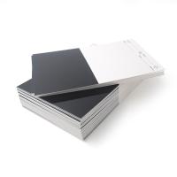
The opacity meter (Fig. 16) consists of a black glass plate 1 with dimensions -140 x 50 x 6 mm. The upper part of the frosted surface of the glass plate is engraved with a scale in millimeters, and there is a back groove 2 with a depth of 2 mm and a width of 10 mm. Along the surface of the glass plate 1, an upper plate 3 with a size of 70 x 35 x 6 mm moves, and a steel plate 4 with a thickness of 0.45 mm is fixed below the plate 3. In this way, between the plate 1 and the plate 3, a wedge-shaped space filled with the sample is formed. Depending on the position of the plate 3, the edge green (groove edge) of the groove 2 may or may not be exposed through the paint layer.

When the plate 3 is moved to the left, that is to say, when the thickness of the paint layer on the side of the tank of the fourth waste 2 is increased, the last right side is not visible. As the plate 3 moves to the right, the lacquer on the bad side of the groove 2 becomes thinner, and this groove side becomes visible again. According to the position of the plate 3 measured on the scale of the plate 1, the thickness of the paint layer when the bad edge is just concealed can be easily calculated.
In order to eliminate the possibility of making mistakes, move the plate 3 to the right until the dividing line appears, and then move the plate 3 to the left until the dividing line disappears; find the arithmetic mean of the scale when the dividing line disappears and appears value. Moving the glass plate to the left and right is necessary because changes in intensity can be measured by eye with an accuracy of only 1% to 2%. It is difficult to measure the hiding power of black, red, blue and other dark pigments on this instrument, because when testing these pigments, the bad edge of the dimple 2 will not be revealed on the black base color (background) of. When experimenting with these pigments, a glass plate (without grooves) fused from two pieces of glass (black and white) that meet at the dividing line can be used.
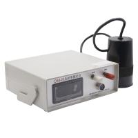
In order to measure the hiding power more objectively with the hiding power meter, a photoelectric circuit diagram can be used, that is, a small chamber with a photoelectric tube is placed under the lower glass plate, and a small chamber with a light source is placed on the upper glass plate. small room.
A schematic diagram of the photoelectric hiding power meter is shown in Figure 17.
The calculation process of pigment hiding power is as follows 2. From the triangle MKa (Figure 18), the critical thickness Ka of the base paint when the edge of the four grooves is hidden can be measured:

It can be seen that after determining the position of the glass plate 3 (refer to Figure 16) and multiplying the reading on the scale by 0.0064, the critical thickness of the paint layer when the paint begins to reveal is obtained.
If the paint can cover when the paint layer thickness D=0.0064, then 6400K mm3 of this paint is required on the painted surface of 1 m2, or 6.4K cm3/m2, or 6_4Kd g/m ' or here expresses the specific gravity of the paint.
It is known that P represents the content percentage of the pigment in the paint, and the hiding power of the pigment can be calculated according to the following formula: