1 Overview
1.1 Scope of Application
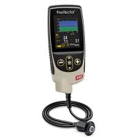
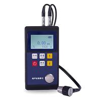
The TT300 series ultrasonic Thickness Gauge (including basic TT310, high temperature TT320, cast iron TT340) adopts the ultrasonic measurement principle, which is suitable for the measurement of the thickness of various materials that can make the ultrasonic wave propagate inside it at a constant speed and can be reflected from its back.
The instrument enables accurate measurement of all kinds of plates and all kinds of machined parts, and another important aspect is that it can monitor the various pipes and pressure vessels in the production equipment and monitor the degree of thinning of them after corrosion during use. It can be widely used in petroleum, chemical industry, metallurgy, shipbuilding, aviation, aerospace and other fields.
1.2 Rationale
The principle of ultrasonic thickness measurement is similar to that of light wave measurement. The ultrasonic pulse emitted by the probe reaches the measured object and propagates through the object.
When it reaches the material interface, it is reflected back to the probe and the thickness of the material is determined by accurately measuring the time it takes for the ultrasonic waves to propagate through the material.
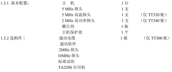
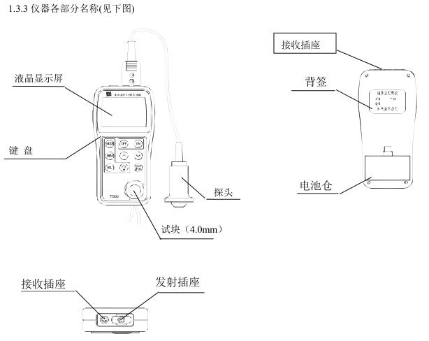
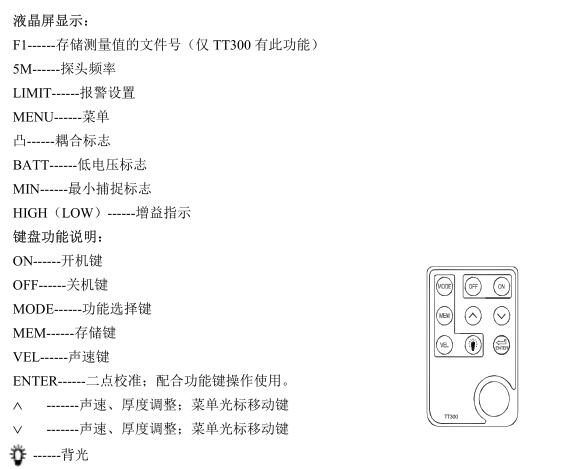
1.3 Basic configuration and the name of each part of the instrument
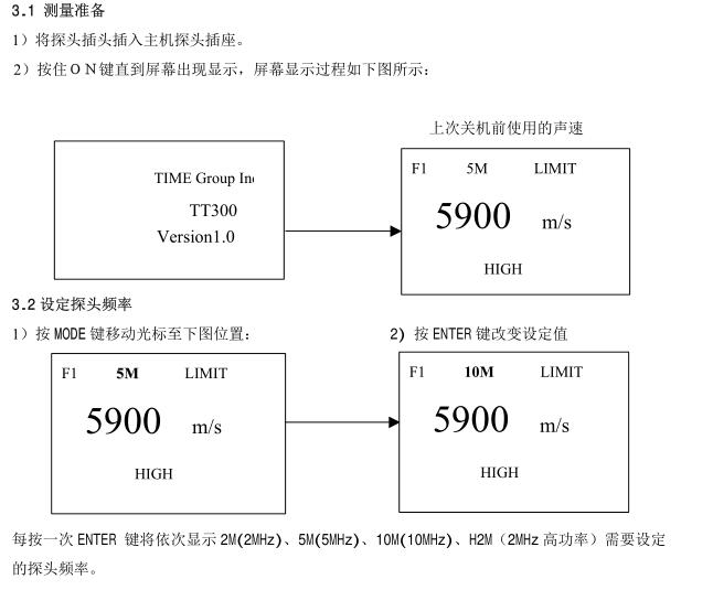
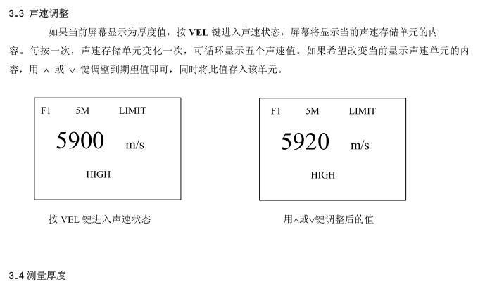
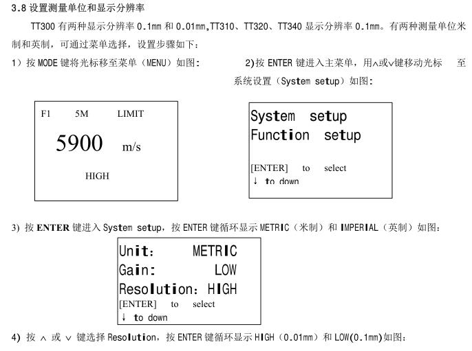
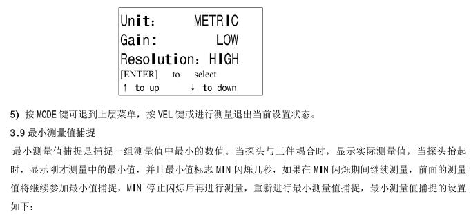
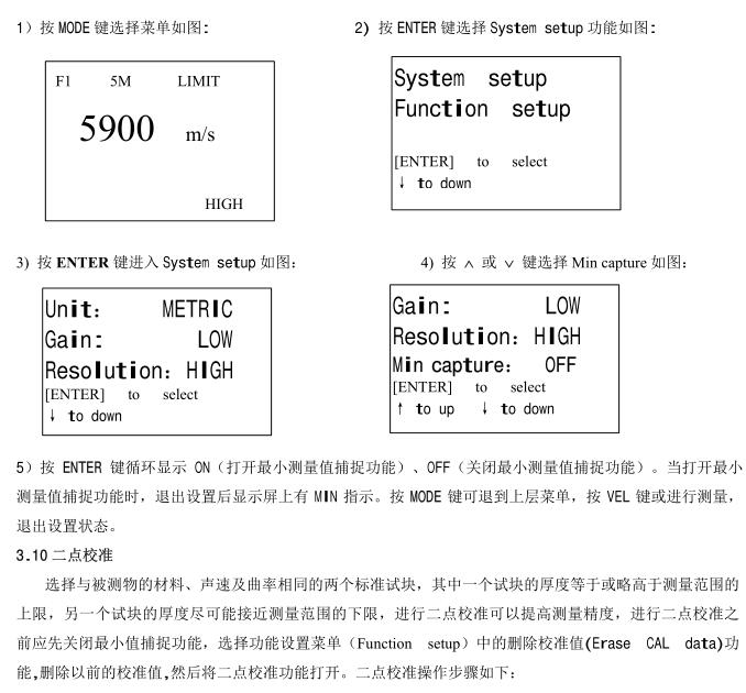
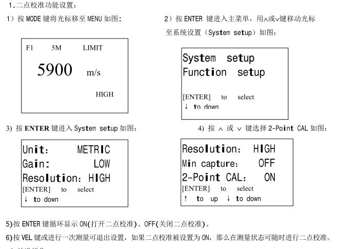
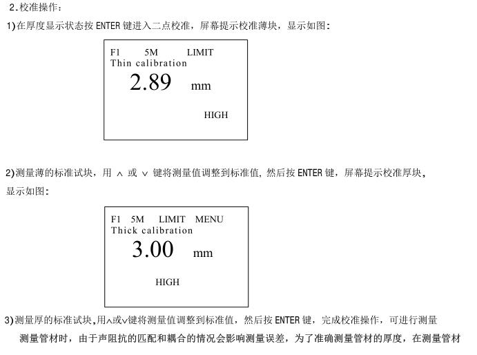
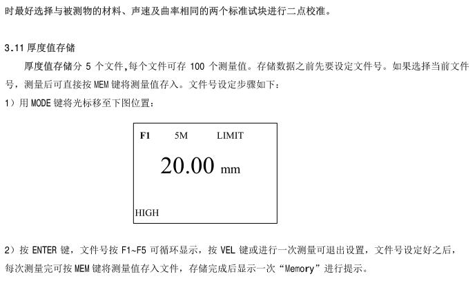
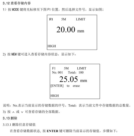
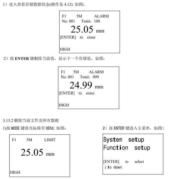
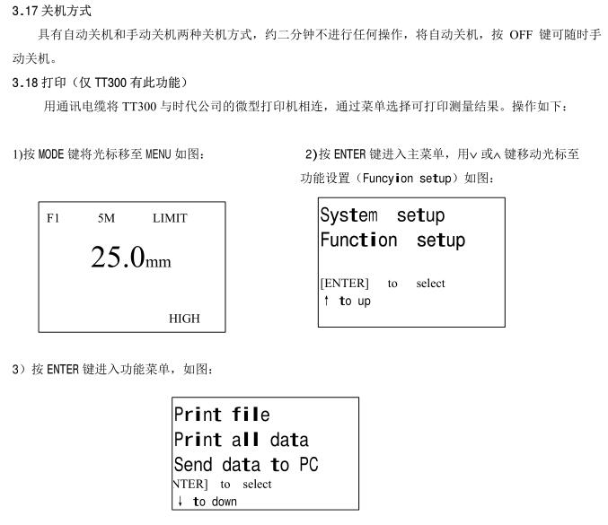
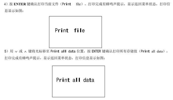
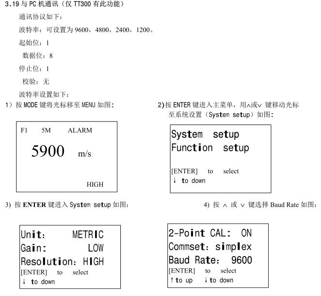
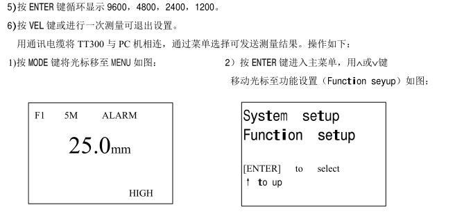
3. Measurement and operation


4. Measurement technology
4.1 Clean the surface
Before measuring, all dust, dirt and rust should be removed from the surface of the measured object, and paint and other covering materials should be removed.
4.2 Improve roughness requirements
Excessively rough surfaces can cause measurement errors or even no readings on the instrument. Before measuring, the surface of the tested material should be smoothed as much as possible.
Throwing, filing and other methods make it smooth. High-viscosity couplants can also be used.
4.3 Rough machined surface
Regular grooves caused by rough-machined surfaces (e.g. lathes or planers) can also cause measurement errors, which can be compensated in the same way as in 4.2, but adjusted separately
The angle between the whole transducer crosstalk separator plate (passing through the thin metal layer in the center of the bottom surface of the probe) and the groove of the measured material makes the separator plate and the slot perpendicular or parallel to each other, and the minimum value in the reading is taken as the thickness of the measurement, which can achieve good results.
4.4 Measure cylindrical surface
For the measurement of cylindrical materials, such as pipes, oil drums, etc., the importance of selecting the angle between the transverse barrier plate of the probe and the axis of the material to be measured is not to be overstated. To put it simply, the probe is coupled to the material to be measured, the transducer crosstalk barrier plate is parallel or perpendicular to the axis of the material being measured, and the probe is slowly shaken perpendicular to the axis of the material being measured, and the readings on the screen will vary regularly, selecting the minimum value in the reading as the exact thickness of the material.
The criterion for selecting the angle of intersection between the probe crosstalk barrier plate and the axis of the material to be measured depends on the curvature of the material, and the probe is selected for the larger diameter tube
The crosstalk partition plate is perpendicular to the axis of the pipe, and the pipe with a smaller diameter is parallel to the axis of the pipe and perpendicular to the measurement method, and the minimum value in the reading is taken as the measurement thickness.
4.5 Composite shape
When measuring materials with composite shapes (such as pipe elbows), the method introduced in 5.4 can be used, but the difference is that a secondary measurement is required
Do not read the transcultural barrier plate perpendicular to the axis and the smaller number as the thickness of the material at the measurement point.
4.6 Non-parallel surfaces
In order to obtain a satisfactory ultrasonic response, the other surface of the material to be measured needs to be parallel or coaxial to the surface being measured, otherwise it will cause a measurementError or no reading at all.
4.7 Influence of temperature of materials
The thickness of the material and the ultrasonic propagation speed are affected by the temperature, if the measurement accuracy is required to be high, the test block comparison method can be used, that is, the test block of the same material is measured under the same temperature conditions, and the temperature compensation coefficient is obtained, and the measured value of the measured workpiece is corrected with this coefficient
4.8 Large attenuation materials
For some materials such as fibers, porous, and coarse-grained materials, they can cause a large amount of ultrasonic scattering and energy attenuation, resulting in abnormal or even no readings (usually abnormal readings are less than the actual thickness), in which case the material is not suitable for testing with this thickness gage.
4.9 Reference test blocks
Precise measurements are made on different materials under different conditions, and the closer the material of the calibration block is to the material being measured, the more accurate the measurement. A satisfactory reference block will be a set of test blocks of different thicknesses of the material to be measured, and the test block can provide the instrument to compensate for the correction factors (such as the microstructure of the material, heat treatment conditions, particle direction, surface roughness, etc.). In order to meet the requirements for maximum accuracy measurements, a set of reference test blocks will be important.
In most cases, satisfactory measurement accuracy can be achieved using a reference block of the same material and a similar thickness as the material being measured. Take the uniform material to be measured with a micrometer and use it as a test block.
For thin materials, when its thickness is close to the lower limit of the probe measurement, the test block can be used to determine the exact low limit. Do not measure materials below the lower limit thickness. If a thickness range can be estimated, then the upper limit of the thickness of the test block should be selected.
When the tested material is thick, especially the alloy with complex internal structure, one should be selected in a group of test blocks that is close to the tested material.to make it easier to master calibration.
In order to solve this problem, the test block should have an internal structure in the same direction as the measured material, and the sound wave propagation direction in the test block should also be the same as the direction in the tested material.
In some cases, the sound velocity gauge of a known material can be used as a substitute for a reference test block, but this is only an approximate substitute for some reference test blocks, and in some cases, the value in the sound velocity gauge is different from the actual measurement, because the physical and chemical conditions of the material are different. This method is often used to measure mild steel, but only as a rough measurement.
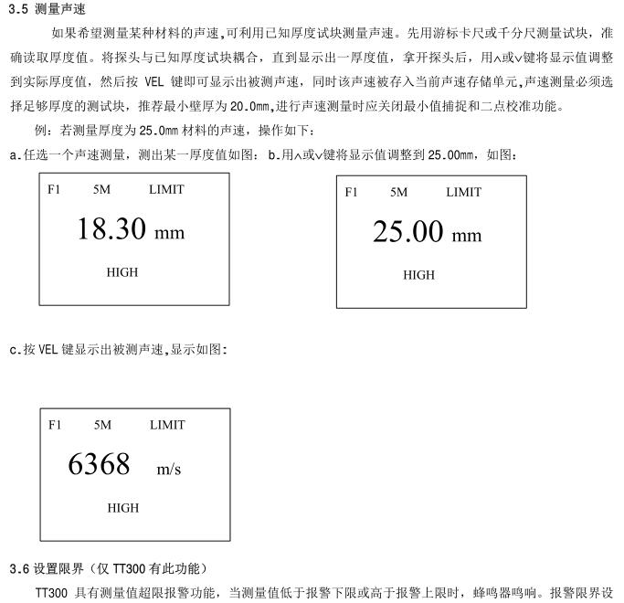
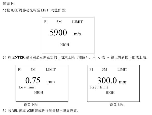
The TT300 ultrasonic Thickness Gauge has the function of measuring the speed of sound, so that the speed of sound can be measured first, and then the workpiece can be measured at that speed.
4.10 Several Methods in Measurement
a) Single measurement method: Measurement at a point.
b) Double measurement method: two measurements are made with the probe at one point, and the transducer crosstalk partition plate should be perpendicular to each other in the two measurements. choose
The minimum value in the reading serves as the exact thickness of the material.
c) Multi-point measurement method: multiple measurements are carried out within a certain measurement range, and the minimum value is taken as the material thickness value.
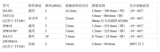
4.11 Probe Selection
4.12 The wear of the transverse sound barrier plate of the probe will affect the measurement, and the probe should be replaced when the following phenomena occur.
1. When measuring different thicknesses, their measurements always show a certain value.
2. When the probe is plugged in, there is an echo indication or a measured value without measurement.
4.13 Casting measurement
Casting measurement has its peculiarities. The grain of the casting material is relatively coarse, the structure is not dense enough, and it is often measured in the state of the rough surface, so it is difficult to measure the large.
The first is the coarseness of the grains and the non-compactness of the structure that causes a great attenuation of sound energy, which is caused by the scattering and absorption of sound energy by the material. The degree of attenuation is closely related to the grain size and ultrasonic frequency, and the attenuation increases with the increase of grain diameter at the same frequency, but there is a highest point, beyond which the grain diameter increases again, and the attenuation basically tends to a fixed value. The attenuation for different frequencies increases with frequency.
Secondly, due to the coarse grain size and the presence of coarse out-of-phase structure in the casting, abnormal reflections, i.e., grass-like echoes or tree-like echoes, will cause false readings and misjudgments.
In addition, as the grains become coarse, the elastic anisotropy in the direction of the metal crystallization becomes more significant, resulting in the velocity of sound in different directions
This can make a difference, with a maximum difference of up to 5.5%. In addition, the compactness of the tissues at different points within the workpiece is inconsistent, which also causes differences in sound velocity. These will result in inaccuracies in the measurements. Therefore, special care should be taken with the measurement of castings.
When measuring castings, you should pay attention to:
1. When measuring castings with unprocessed surfaces, it is necessary to use oil, butter and water glass with high viscosity as couplant.
2. It is better to use the same material as the DUT and measure the same direction as the standard test block to calibrate the sound velocity of the material.
3. Two-point calibration can be carried out if necessary.
5. Prevention methods for measurement errors
5.1 Ultra-thin materials
With any ultrasonic Thickness Gauge, the thickness of the material to be measured falls below the lower limit of the transducer's use, resulting in measurement errors, and if necessary, the minimum limit thickness can be measured using the block comparison method.
When measuring ultra-thin materials, sometimes an error result called "double refraction" occurs when the displayed reading is twice the actual thickness, and another error result is called "pulse envelope, cyclic jump", which results in a value that is larger than the actual thickness.
5.2 Rust spots, corrosion pits, etc
Rust spots and pits on the other surface of the material to be measured will cause irregular changes in readings, and in extreme cases, even no readings, and small rust spots are sometimes difficult to detect. When a pit is found or when doubts are made, this area needs to be measured with great care, and the probe can be positioned at different angles for multiple tests.
5.3 Material Identification Errors
When an instrument is calibrated with one material and then tested with another, incorrect results will occur and care should be taken to select the correct sound velocity.
5.4 Wear and tear of the probe
The surface of the probe is made of acrylic resin, which will increase the roughness and reduce the sensitivity due to long-term use, and the user can use sandpaper or stone to smooth the surface of the probe with a small amount of sandpaper or stone to ensure the parallelism if it can be determined that the error is caused by this reason. If it is still unstable, the probe will need to be replaced.
5.5 laminated materials, composite materials
It is not possible to measure uncoupled laminated materials because ultrasound waves cannot penetrate uncoupled spaces. In addition, because ultrasonic waves cannot propagate at a uniform speed in composite materials, instruments that measure thickness by the principle of ultrasonic reflection are not suitable for measuring laminated materials and composite materials.
5.6 Effect of oxide layer on metal surface
Some metals can produce a dense oxide layer on their surface, such as aluminum, etc., which is tightly bound to the substrate and has no obvious interface.
However, the propagation speed of ultrasonic waves in these two substances is different, so it will cause errors, and the size of the error is different in the thickness of the oxide layer, please pay attention to it when using, and you can choose a piece of the same batch of tested materials to be measured with a micrometer or caliper to make a sample block, and calibrate the instrument.
5.7 Unusual thickness readings
The operator should have the ability to identify anomalous readings, which are usually caused by rust spots, corrosion pits, and internal defects in the material being measured. The solution can be found in chapters 5 and 6.
5.8 Use and selection of couplant
The couplant is used as a high-frequency ultrasonic energy transfer between the probe and the material being measured. If you choose the type or use it incorrectly, there will be
This may cause errors or flickering coupling markers that make it impossible to measure values. The couplant should be used in moderation and evenly coated.
It is important to select the right kind of couplant, and when used on smooth material surfaces, low viscosity couplants (e.g., randomly configured couplant, light motor oil, etc.) are suitable. When used on rough material surfaces, or on vertical surfaces and top surfaces, highly viscous couplants (e.g. glycerin paste, butter, grease, etc.) can be used.
Couplant formulations are available everywhere.
6 precautions
6.1 Cleaning of test blocks
Since the couplant is applied to the instrument using a random test block, it is necessary to take care to prevent rust. Wipe the random test block clean after use. gasDo not sweat when the temperature is high. If it is not used for a long time, a little grease should be applied to the surface of the random test block to prevent rust, and when it is used again, the grease will be wiped off and it can work normally.
6.2 Cleaning of the casing
Alcohol, diluent, etc. have a corrosive effect on the casing, especially the window, so when cleaning, gently wipe with a small amount of water.
6.3 Probe protection
The probe surface is acrylic and sensitive to rescratching of rough surfaces, so it should be gently pressed in use. When measuring rough surfaces, minimize the scratching of the probe on the working surface.
When measuring at room temperature, the surface of the analyte should not exceed 60°C, otherwise the probe can no longer be used.
The adhesion of oil and dust will gradually age and break the probe cable, and the dirt on the cable should be removed after use.
6.4 Replacement of Batteries
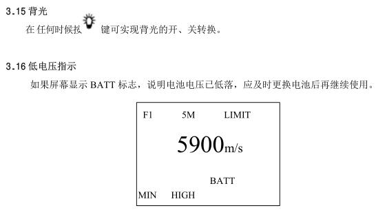
After the low voltage indication sign appears, the battery should be replaced in time as follows:
a. Shut down
b. Open the battery compartment cover
c. Take out the battery and put in a new battery, noting the polarity
When the instrument is not in use for a long time, the battery should be taken out to avoid battery leakage and corrosion of the battery box and pole piece.
6.5 Strictly avoid collision, moisture, etc.
7. Repairs
7.1 If the error of the measured value is too large, please refer to Chapters 6 and 7.
7.2 If there are any of the following problems, please contact the maintenance department of Times Group:
A instrument device is damaged and cannot be measured.
B LCD display is not normal.
C When used normally, the error is too large.
D. Keyboard operation is out of order or out of order.
7.3 Since TT300 series ultrasonic Thickness Gauge is a high-tech product, the maintenance work should be completed by professionally trained maintenance personnel, please do not disassemble and repair by yourself.