1 Overview
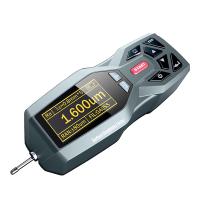
TR200 Handheld Roughness Meter is another new product developed by Times Group Corporation. This instrument is suitable for the production site and can measure the surface roughness of various machined parts. It can calculate the corresponding parameters according to the selected measurement conditions and display them on the LCD All measurement parameters and contour graphics are clearly displayed on the screen.
Features:
Multi-parameter measurement: Ra, Rz, Ry, Rq, Rp, Rm, Rt, R3z, Rmax, Sk, S, Sm, tp;
High precision inductive sensor;
RC, PC-RC, GAUSS, DP four filtering methods;
Compatible with ISO, DIN, ANSI, JIS four standards;
128×64 dot matrix LCD, which can display all parameters and graphics;
Using DSP chip for control and data processing, fast speed and low power consumption;
Built-in lithium-ion rechargeable battery and charging control circuit, high capacity, no memory effect, continuous working time is more than 20 hours;
Mechatronic design, small size, light weight, easy to use;
Connect to Times TA220s printer to print all parameters and outline graphics;
Built-in standard RS232 interface, can communicate with PC;
With automatic shutdown, memory and various prompts and instructions;
Optional surface sensor, small hole sensor, measuring platform, sensor sheath, extension rod and other accessories.
1.1 Measuring principle
When measuring the surface roughness of the workpiece, the sensor is placed on the measured surface of the workpiece, and the driving mechanism inside the instrument drives the sensor to slide along the measured surface at a constant speed. The sensor feels the roughness of the measured surface through the built-in sharp stylus. The roughness of the measured surface of the workpiece causes the displacement of the stylus, and the displacement changes the inductance of the inductance coil of the sensor, so that an analog signal proportional to the roughness of the measured surface is generated at the output of the phase-sensitive rectifier. After amplification and level conversion, it enters the data acquisition system, and the DSP chip performs digital filtering and parameter calculation on the collected data, and the measurement results are read out on the LCD, output on the printer, and can also communicate with the PC.
1.2 Standard configuration

1.3 Names of each part of the instrument


1.4 Basic connection method
1.4.1 Sensor loading and unloading
When installing, hold the main part of the sensor with your hand, insert the sensor into the sensor connection sleeve at the bottom of the instrument as shown in Figure 1-2, and then push it to the end. When disassembling, hold the main part of the sensor or the root of the protective sleeve by hand, and pull it out slowly.

1.4.2 Power Adapter and Battery Charging
When the battery voltage is too low, that is, when the battery voltage prompt on the display shows that the voltage is too low and flashes, the instrument should be charged as soon as possible. When charging, first put the battery switch at the bottom of the instrument in the ON position, then insert the power plug of the power adapter into the power socket of the instrument as shown in Figure 1-3, and then connect the power adapter to the 220V50Hz mains, that is, Start charging. The input voltage of the power adapter is 220 volts AC, the output is 6 volts DC, the maximum charging current is about 500 mA, and the longest charging time is about 2.5 hours. This instrument uses a lithium-ion rechargeable battery, which has no memory effect and can be charged at any time, and the instrument can work as usual when charging.


2Measurement operation
2.1 Preparation before measurement
a. Turn on the machine and check whether the battery voltage is normal;
b. Wipe the measured surface of the workpiece;
c. Referring to Figure 2-1 and Figure 2-2, place the instrument correctly, stably and reliably on the surface of the workpiece to be tested;


5Daily maintenance and maintenance
Avoid collisions, violent vibrations, heavy dust, humidity, oil, strong magnetic fields, etc. The sensor is a precision part of the instrument and should be carefully maintained. After each use, put the sensor back into the packing box; the random standard sample should be carefully protected, so as not to cause the calibration instrument to be out of alignment after being scratched.

5.1 Troubleshooting
If the instrument fails, first deal with it according to the measures provided in the fault information in the next section. If it still cannot be eliminated, return it to the manufacturer for maintenance. Users are not allowed to disassemble or repair by themselves. The instrument sent back to the manufacturer for maintenance shall be accompanied by a warranty card and a standard model provided with it, and the failure phenomenon shall be explained.
6 battery switch
As shown in the figure below, the switch at the bottom of the instrument is the battery switch.

1. When charging, the battery switch must be in the ON position, otherwise the battery will not be charged.
2. When not in use for a long time, please put the battery switch in the OFF position.
3. When the instrument leaves the factory, the battery switch is in the OFF position, and the user needs to put the battery switch in the ON position before using it.
If the instrument does not turn on after turning on the battery switch, just press the power button.
4. If the instrument is not working properly, and the problem cannot be solved by turning off and on, you can turn off the battery switch and wait 10 seconds.
Open after the clock.
7 References
7.1 Contours and filters
7.1.1 Profile
a. Unfiltered contour: the unfiltered contour signal picked up by the sensor from the measured surface. b. Filtered profile: the profile signal after the original profile has been filtered to remove the waviness component.
7.1.2 Filters
a.RC: Traditional second-order RC filter with phase difference; b.PC-RC: Phase-corrected RC filter;
c.GAUSS (Gaussian filter): DIN4777
dD-P (Direct Profile): median line using least squares method.
7.2 Driving stroke length