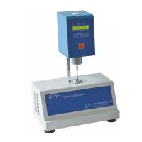
NDJ-1 rotary viscometer application
NDJ-1 rotary viscometer is a new instrument used to measure the viscous resistance of liquid and the absolute viscosity of liquid. It is widely used to measure the viscosity of various fluids such as oil, paint, food, medicine, adhesive, etc.
NDJ-1 rotary viscometer structure principle:
1. The gear system and clutch are used to change the speed, operated by a special rotary knob, and the speed is divided into four gears, which can be selected according to the measurement needs.
2. According to the different specifications of the instrument, there are 4 kinds of rotors from 0 to 4, which can be selected according to the viscosity of the liquid to be measured along with the speed.
3. The instrument is equipped with a fixed pointer control mechanism for accurate readings. When the rotation speed is fast (30 rpm, 60 rpm), it is impossible to read while rotating. At this time, you can press the pointer control lever to fix the pointer for easy reading.
4. The protective frame is to stabilize the measurement and protect the rotor. Using the protective frame to measure can obtain more stable measurement results. The yellow protective ring is to protect the connecting rod of the instrument shaft from external forces affecting the accuracy and stability of the instrument.
5. The instrument can be used by hand and is equipped with a fixed bracket and a lifting mechanism. Generally, it should be used fixedly when performing small-scale and constant temperature measurements in the laboratory.
NDJ-1 rotary viscometer installation:
1. Take out the storage box, bracket and three adjustment screws from the packing box.
2. Screw the three adjustment screws into the feet of the stand.
3. Check the flexibility and self-locking of the lifting chuck. If it is found to be too loose or too tight, you can use a Phillips screwdriver to adjust the tightening screw of the chuck so that it can be lifted up and down. Generally, it is better to be slightly tighter, so as to prevent it from occurring after installing the viscometer. Fall automatically.
4. Open the storage box, take out the viscometer, put the viscometer into the lifting chuck, tighten it with the handle fixing screw (should be as horizontal as possible), take off the rubber band on the pointer control rod, and take off the yellow protective ring at the lower end of the viscometer, Then take out the protective frame in the storage box and spin it on the viscometer.
5. Use the adjusting screw to adjust the level bubble to keep the viscometer level.
NDJ-1 rotary viscometer operation and use:
1. Prepare the liquid to be tested, place it in a beaker or a straight container with a diameter of not less than 70mm and a height of not less than 130mm, and accurately control the temperature of the liquid to be tested.
2. Install the protection frame on the instrument (screw right to install, and left to remove).
3. Screw the optional rotor into the shaft connecting rod (screw it to the left to install it, and turn it to the right to remove it). Rotate the lifting knob to lower the instrument slowly, and gradually immerse the rotor in the liquid to be measured until the rotor liquid level mark and the liquid level are level, and then fine-tune the level. Turn on the power, press the pointer control lever, turn on the motor, turn the variable speed knob to the selected speed, release the pointer control lever, and read when the pointer is stable. It usually takes about 30 seconds. When the speed is running at the "6" or "12" gear, the pointer can be read directly after it stabilizes; when the speed is at the "30" or "60" gear, press the pointer control lever after the pointer is stable, and the pointer turns to the display window , turn off the power to take a reading. Note: Do not use excessive force when pressing the pointer lever. Mastery can be practiced while idling.
4. When the value pointed by the pointer is too high or too low, you can change the rotor and speed, so that the reading is preferably between 30 and 90 divisions.
5. Use the No. 0 spindle and the low viscosity fluid test accessory to perform the following procedure.
5.1 Install the No. 0 rotor on the connecting screw (rotate to the left to install).
5.2 Insert the fixing sleeve into the cylinder at the bottom of the instrument, and tighten it with the sleeve fixing screw.
5.3 When equipped with an outer test cylinder with a bottom, inject 20-25ml of the liquid to be tested into the outer test cylinder and then operate according to the following steps. When equipped with a bottomless outer test cylinder, the following steps can be directly followed.
5.4 Put the outer test tube into the fixing sleeve and tighten it with the test tube fixing screw. When tightening, pay attention that the tapered end of the test tube fixing screw is screwed into the triangular groove on the upper end of the outer test tube (it can be inserted into the round hole on the side). Observe whether the triangular groove of the test tube is in the center of the round hole). The test can be carried out after controlling the temperature of the liquid to be tested.
5.5 When the outer test cylinder and the rotor are immersed in the liquid, take the red dot on the fixed sleeve as the liquid level line.
6. Selection of range, coefficient, rotor and speed:
6.1 First roughly estimate the viscosity range of the liquid to be measured, and then select the appropriate rotor and speed according to the range table. For example: when measuring the liquid of about 3000mpa?s, the following coordination can be used: No. 2 rotor...6 rpm, or No. 3 rotor...30 rpm
6.2 When the approximate viscosity of the liquid to be tested cannot be estimated, it should be assumed to be a higher viscosity, and try the rotors from small to large (the size refers to the shape, the same below) and the speed from slow to fast. The principle is that a small rotor and a slow speed are used for high viscosity liquids; a large rotor and fast speed are used for low viscosity liquids.
6.3 Coefficient: When measuring, the reading indicated by the pointer on the dial needs to be multiplied by the specific coefficient on the coefficient table to obtain the measured absolute viscosity (mpa?s).
That is, η=k?α
In the formula: η = absolute viscosity
k = coefficient
α = the reading indicated by the pointer (deflection angle)
6.4 Correction of frequency error: When the frequency of the power supply is inaccurate, it can be corrected according to the following formula. Nominal frequency actual viscosity = indicated viscosity / actual frequency
Notes for NDJ-1 rotary viscometer
1. This instrument is suitable for use in normal temperature environment.
2. The instrument needs to be measured within the specified frequency and voltage tolerance range, otherwise the measurement accuracy will be affected.
3. As far as possible, use the bracket to fix the instrument for measurement. If the handheld operation should keep the instrument stable and level.
4. Care should be taken when loading and unloading the rotor. When assembling and disassembling, the connecting screw should be lifted slightly for operation. Do not use too much force or force the rotor laterally, so as not to affect the accuracy of the instrument.
5. Do not place the instrument on its side or upside down with the rotor installed.
6. Do not operate the motor without pressing the pointer lever. Be sure to change the speed while the motor is running.
7. The connection end face and thread of the connecting screw and rotor should be kept clean, otherwise it will affect the correct connection of the rotor and the stability of rotation.
8. When the instrument is raised or lowered, the instrument should be supported by hand to prevent the instrument from falling under its own weight.
9. After each use, the rotor should be cleaned in time (do not clean the rotor on the instrument), and it should be properly placed in the rotor rack after cleaning.
10. After installing the No. 0 rotor, do not "spin" without fluid, so as not to damage the shaft tip.
11. There is no need for a protective frame when using rotor 0.
12. Do not dismantle, adjust, and instrument parts at will, and do not add lubricating oil by yourself.
13. When the instrument is moved and transported, the pointer control rod should be encircled by a rubber band, and inserted into the yellow packaging ferrule to support the connecting screw rod, and then tightened with the screw.
14. Suspensions, emulsions, polymers and other high-viscosity liquids are mostly "non-Newtonian liquids", and their apparent viscosity changes with shear speed and time. It is normal for the results to be inconsistent, not because the instrument is inaccurate (generally, the determination of non-Newtonian liquids should specify the rotor, rotational speed and time).
15. Accurate values can be obtained by doing the following points:
. Accurately control the temperature of the measured liquid.
.The temperature of the rotor and the protective frame is consistent with that of the measured liquid.
.Keep the uniformity of the measured liquid without air bubbles.
.Place the rotor at the center of the container and the liquid level marking line as much as possible during the measurement.
.Prevent air bubbles from adhering to the bottom or surface of the rotor when the rotor is immersed in liquid.
.When changing the rotor or rotating speed, the reading on the dial should be higher, and α should be between 30 and 90 divisions as much as possible.
.Use a protective stand for measurement.
.Ensure that the rotor and connecting screws are clean.
. For liquids lower than 15mpa?s, choose No. 0 rotor.
.When the power frequency is not accurate, correct it according to the correction formula.
.The horizontal bubble is adjusted correctly, and the instrument should be slowly moved up and down to keep the instrument stable.
. After the pointer is stable on the dial, read with the same viewing angle.
.Strictly operate in accordance with the operating procedures.