Before the measurement, insert the thermometer into the shuttle mirror group 13 and tighten it; after passing through the constant temperature water for about 20 minutes, make the shuttle mirror reach the specified temperature.
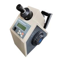
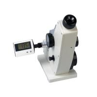
1. Clean the surface of the rear mirror, add the liquid to be tested to the frosted surface of the light entrance shuttle mirror with a dropper, and turn the shuttle mirror to lock the handle (12 of Figure 7-16).
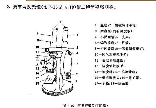
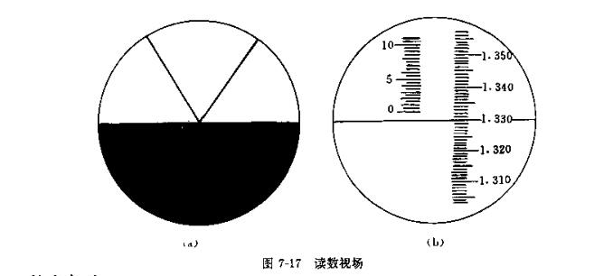
3. Rotate the handwheel 2 to rotate the prism group 13, observe the light-dark boundary line moving up and down in the eyepiece, and rotate the Amici prism handwheel 10 at the same time so that there are no other colors in the field of view except black and white. When the boundary line is at the center of the crosshair [Figure 7_17(a)], observe the scale value indicated on the right side of the field of view of the reading mirror [Figure 7-17(b)] is the measured refractive index (ND).
Precautions:
1. The instrument should be placed in a dry environment to avoid moldy optical parts. After each use, wipe the prism clean with special lens cleaning paper and put it in the wooden area.
2. The liquid to be tested dropped into the prism should evenly fill the field of view without air bubbles. When measuring volatile substances, the test liquid should be replenished in the small hole on the side of the prism group during the measurement process.
3. Before using the refractometer, the accuracy of the instrument should be checked by the refractive index of the standard material. Its operation method is as follows:
Stick the standard crystal block marked with the refractive index on the polished surface of the refracting prism (upper block) in prism group 13 (see Figure 7-16) with a-bromine, do not close the light entrance prism (lower block) . Open the protective cover 16, let the light enter from it, rotate the hand wheel 2, and the reading of the refractive index in degrees refers to the value given by the standard crystal block, and then observe through the telescope whether the black self-dividing line is in the middle of the cross line, as shown in Figure 7 -l7Ca). If there is a deviation, adjust the screw 9 so that the position is as shown in Figure 7-l7(a).
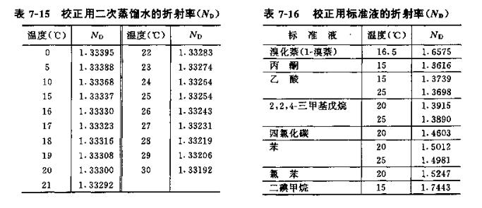
In addition, it can also be directly measured with secondary plain water or standard water, and observe whether the reading is consistent with the standard value. If there is a deviation, adjust the screw 9 to make it consistent.
The standard values of plain tube water and some standard solutions are listed in Table 7-15 and Table 7_16 respectively.