Development of the ISO outFlow Cup
The standard outFlow Cups of various countries in the world have different measured viscosity values due to the different volume and size of the outflow hole. Although various countries are equipped with outFlow Cups with different apertures to form a series in order to expand the measurement range of viscosity, such as the American Ford cup and the German DIN cup, each has a set of 5, but the lack of interchangeability still affects international technical exchanges. In order to standardize the design of outFlow Cups and improve flow stability, and to unify the size of outFlow Cups in various countries and facilitate the comparison of measured values, the International Organization for Standardization proposed an improved ISO outFlow Cup.
In the first edition of the international standard "ISO 2431 Paints and varnishes - Determination of outflow time by outFlow Cup" published in 1979, only one outFlow Cup with an aperture of 4 mm was specified. In the second edition, three kinds of outFlow Cups with hole diameters of 3 mm, 4 mm and 6 mm are changed, which are called No. 3 cup, No. 4 cup and No. 6 cup respectively. When the fourth edition was promulgated in 1993, four outFlow Cups with apertures of 3 mm, 4 mm, 5 mm and 6 mm were added. It can be seen that the development of the ISO outFlow Cup is gradually serialized and continuously improved and improved.
The structure and professionalism of the ISO outFlow Cup
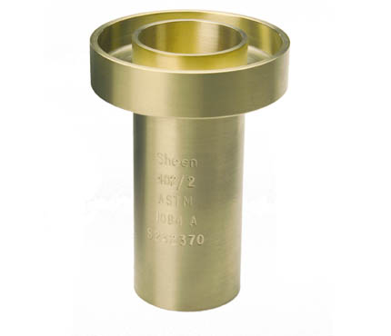
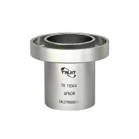
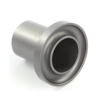
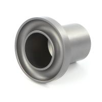
The ISO outFlow Cup is also a container with a cylindrical upper part and a conical lower part. The bottom of the cone is an elongated small cylindrical leak nozzle. There is a protective sleeve on the outside to prevent the protruding mouth of the outFlow Cup from being accidentally damaged.
The reasonable professionalism of the ISO outFlow Cup is that the cone angle is 120°, which is larger than that of the Tu-4 cup (the Tu-4 cup is only 81°), which more effectively overcomes the turbulence caused by the liquid entering the outflow hole. Secondly, the length of the outflow hole of the ISO outFlow Cup is 20 mm, and the ratio of the length to the hole diameter, that is, L/D, is 5, while the L/D of the Tu-4 cup is only 1. The larger the value of L/D, the better the capillary action of the outflow hole. The more pronounced, the more stable the liquid flow. In addition, the viscosity test range of the ISO outFlow Cup is wide, and the outFlow Cups with different apertures have different kinematic viscosity ranges of the test samples. The test range of No. 3 cup is 7 ~ 42mm2/s, No. 4 cup is 34 ~ 135 mm2/s, No. cup 91 ~ 326 mm2/s, No. 6 cup 188 ~ 684 mm2/s, its serialization not only increases the test range, but also improves the test accuracy. Although the design of the ISO outFlow Cup is more professional than the existing standard outFlow Cups in various countries, but Its scope of application is still limited to products with Newtonian or near-Newtonian fluid coatings. Attention should be paid to the choice of the aperture of the outFlow Cup before the test, that is, the outflow time of the tested sample in the outFlow Cup is preferably between 30 seconds and 100 seconds. If it exceeds 100 seconds, due to the delay effect, the cut-off point will be difficult to determine, and Poor repeatability.
Calibration of the ISO outFlow Cup
OutFlow Cups with different apertures have the following correction formula:
3 mm outFlow Cup V =0 .443 t -(200/t)
4 mm outFlow Cup V =1 .37 t -(200/t)
5 mm outFlow Cup V =3 .28 t -(200/t)
6 mm outFlow Cup V =6 .90 t -(200/t)
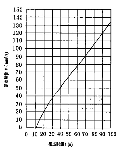
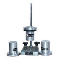
When calibrating the outFlow Cup, standard oil with known kinematic viscosity should be used, and the curve of kinematic viscosity versus temperature should be drawn according to the data provided by the standard oil. Then measure the outflow time of the standard oil at a known temperature (accurate to 0.1 ℃) in the range of 20 ℃ to 30 ℃, and record the outflow time, which should be in the range of 30 seconds to 100 seconds, preferably Near the midpoint of this range, accurate to 0.2 seconds. Then check the kinematic viscosity of the standard oil at this temperature from the drawn graph, and use the correction formula above to calculate the outflow time corresponding to this kinematic viscosity. The calibration curve of each outFlow Cup can also be drawn by the calibration formula, and the figure shows the calibration curve of No. 4 cup. Find the corresponding outflow time of the standard oil from the figure, compare the two outflow times obtained, if the difference between the two values is not more than 3%, it is considered that the outFlow Cup is suitable for use.