The chromatograph data acquisition system designed in this paper uses 24-bit AD chip ADS1253 to convert the voltage signal output by the Detector to analog/digital conversion, and then the data is read by the single-chip microcomputer and sent to the host computer. Mainly introduces the hardware and software design of the system. Among them, the hardware circuit uses the anti-jamming design, and the software design gives the program block diagram. The final experimental results show that the data collected by the system is accurate and reliable, which ensures that the instrument can detect more sample components.
1 Introduction
Chromatographic devices have been used for the preparation of natural substances for hundreds of years. After the advent of commercial high-pressure liquid chromatography in the 1960s, it was quickly adopted for the preparation of natural substances [1]. In recent years, industrial chromatographic devices have become an important method for the purification of natural medicines such as paclitaxel. In terms of laboratory preparation of chromatographic devices, it is currently developing in the direction of high resolution, full component separation and full automation. The chromatographic fillers range from amorphous to spherical, and the particle size ranges from 20-40μm to 5-10μm, which improves the resolution. In terms of chromatographic detection technology, in addition to using the ultraviolet-visible band (UV/VIS) to detect general natural substances, there is also an evaporative light scattering Detector, which solves the inconvenience of the detection of sugars that cannot be detected by UV/VIS and the differential refraction Detector. Problems using gradient elution. Since the function of the chromatograph itself to collect weak signals at the μV level is not strong enough, some sample components cannot be detected and collected. Therefore, in order for the instrument to detect more sample components, it is necessary to design a separate high-precision, high-resolution data collection system.
2 General overview of the system
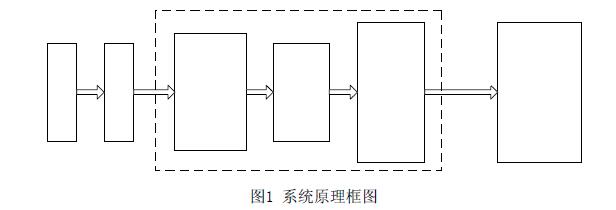
The chromatograph data acquisition system collects the analog voltage signal output by the Detector. The overall system block diagram is shown in Figure 1. Among them, the dotted box is the data acquisition part, which is mainly composed of ADC chip, optocoupler isolation, and single-chip microcomputer. The overall process of the system is as follows: first, the spectral Detector detects the components separated by the chromatographic column of the sample, and outputs an analog signal of tens of μV to hundreds of mV; the analog signal is converted into a digital signal by A/D and then transmitted to the microcontroller ; Finally, the digital signal is transmitted to the upper computer via RS232 by the single chip microcomputer for relevant data processing and analysis.
This system selects the ADS1253 high-speed 24-bit 4-channel AD conversion chip from TI (Texas Instruments, Texas Instruments). number of samples per second), the fastest sampling time reaches 0.048ms, which can meet the application needs. For this project, since the output signal of the Detector is tens of μV to hundreds of mV, the conversion accuracy needs to reach the level of 0.01mV. According to the relevant requirements of the instrument technology, the sampling frequency of the analog signal is designed to be 100Hz.
3 system hardware circuit design
3.1 24-bit ADC circuit design
ADS1253 adopts low-cost but extremely high-resolution Σ-Δ conversion technology, and can obtain more than 20 bit error-free data output, which is very suitable for applications requiring high resolution. When the supply voltage is 5 V and the reference voltage is 1.2 V, the device can directly accept bipolar signals ranging from 0 to ±2.4 V. In order to improve the quality of A/D conversion, ADS1253 also provides a self-calibration function: when the ambient temperature and operating voltage change, or the working state of the chip changes, the self-calibration function can be turned on for a calibration. In order to meet the integration of chromatograph data acquisition system and control system (such as pipeline valve control, mechanical device control, etc.), ATMega64 is selected as the single-chip microcomputer, and the working clock frequency can reach 16M.
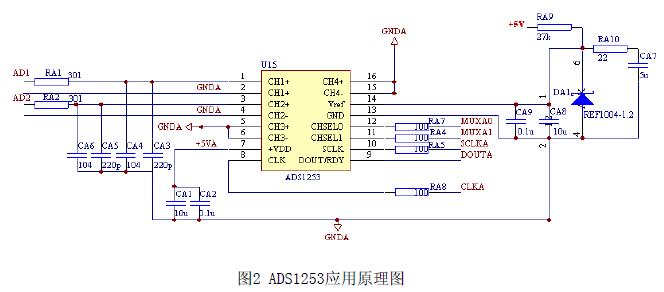
The application schematic diagram of ADS1253 is shown in Figure 2. The dual-channel data acquisition CH1 and CH2 are designed, and the unused input terminals of the other two channels should be grounded. ADS1253 working clock supply method: when the working frequency is below 0.9162M, the square wave generated by the microcontroller can be used as the working clock; when the working frequency is above 1.8432M, the working clock needs to be provided by the crystal oscillator. In this design, the sampling frequency of r is 100Hz, so the working clock is provided by the microcontroller. CLK is the working clock input terminal of the chip, which is connected to the timer I/O port of the microcontroller; the chip REF1004 provides a reference voltage of 1.2V to the Vref pin; the two pins CHSEL0 and CHSEL1 are used to select the four input channels of the chip; The DOUT/RDY pin is used to output the converted 24-bit data result, the SCLK pin is used for the data output clock, and the maximum output data is 7FFFF.
3.2 Anti-interference design
In order to improve the accuracy and stability of AD conversion, the stability of the power supply and the anti-interference performance of the circuit are very important. In the design, a 12V power supply is used to supply power to the MCU expansion board. Two sets of +12V power supplies are generated through the B1212DC-DC isolation circuit, which are respectively passed through the LM7805 After the voltage is stabilized, two isolated 5V working voltages are generated. After filtering, one is supplied to the chip ADS1253, and the other is supplied to the single-chip microcomputer ATMega64. In order to filter out the interference generated on the chip power line, a filter capacitor is connected between the power pin and the ground pin of the ADS1253. There is a 300-ohm resistor and two capacitors of 220pF and 0.1μF on each analog signal input channel. The 220pF capacitor chooses a tantalum capacitor, which has large capacity, stability, and good filtering performance; the 0.1μF capacitor chooses a ceramic capacitor, whose high-frequency impedance is small.
A high-speed photoelectric coupling chip 6N137 is used to isolate the microcontroller and ADS1253. The 6N137 optocoupler is a high-speed optocoupler for a single channel. It is composed of an 850 nm wavelength AlGaAs LED and an integrated Detector. The Detector consists of a photodiode, a high-gain linear op amp and a Schott Base-clamped open-collector transistors. Since there are 5 pins associated between the AD chip and the microcontroller, the circuit needs 5 6N137s for isolation. Two groups of power supplies are used at the input and output ends of the optocoupler, and there is a 0.1μF decoupling capacitor CU131 next to the power supply pin.
4 System software design
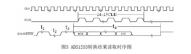
The timing diagram of reading the conversion result of the chip ADS1253 is shown in Figure 3. CLK is the working clock of the chip, SCLK is the data output clock, and DOUT/DRDY is the data output. Before the data output is ready, that is, before t3, SCLK needs to be set low; after the data output is ready, that is, after t4, the SCLK pulse signal can be sent to read the conversion result. The data is shifted on the falling edge of SCLK, and the data is latched on the rising edge. This bit of data appears stably on the DOUT/DRDY data line, and the microcontroller can read this bit of data. Since each data has 24 bits, to read each data, at least 24 SCLK pulse signals need to be sent to read the data completely. Among them, t1 is 24CLK, t2 is 6CLK, t3 is 6CLK, and t4 is 348CLK.
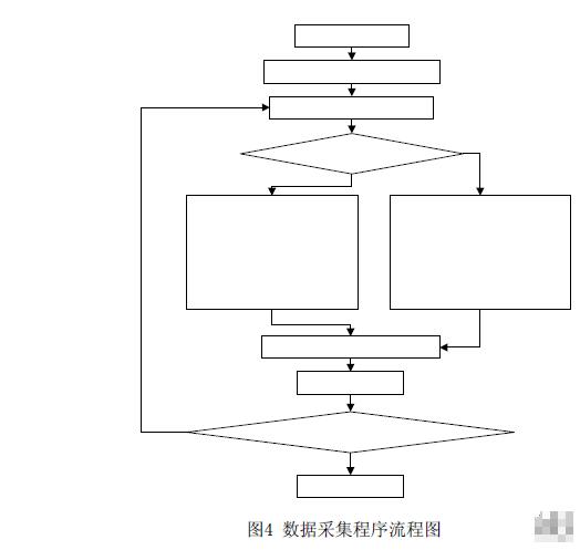
According to the characteristics of chip timing, connect the DOUT/DRDY pin of ADS1253 to the external interrupt pin (INT0) of the microcontroller, and use the external interrupt to capture and calculate the rising and falling edges of the DOUT/DRDY signal to judge t1, t2 and t3 Arrival, once it is found to be the start signal, start the data reading task and start reading the AD conversion result. The 24-bit conversion results need to be sequentially shifted out by the DOUT/DRDY pin under the SCLK pulse, so serial-to-parallel conversion is required inside the ATMega64, and the 24-bit serial data is stored in three bytes through shifting. The DOUT/DRDY pin outputs the high bit first and then the low bit. You can use data[1] to save 24~17 bits first, then use data[2] to save 16~9 bits, and finally use data[3] to save 8~1 bits. The flow chart of the program implementation is shown in Figure 6. The codes are written in C language and compiled on the ICC AVR.
5 Experimental results and analysis
Set the ADS1253 to work in unipolar single-channel continuous conversion mode, the A/D conversion speed is 100Hz, the reference voltage is provided by REF1004, and the input voltage value is measured by a 5.5-digit digital multimeter FLUKE 8842A. The experimental results are shown in Table 1 below. Among them, the reference voltage measured by the 5-digit meter is Vref = 1.23347V. Assuming that the output 3-byte hexadecimal number is Dout, the corresponding voltage Vout conversion formula is: Vout=(1.23347/7FFFF)*Dout.
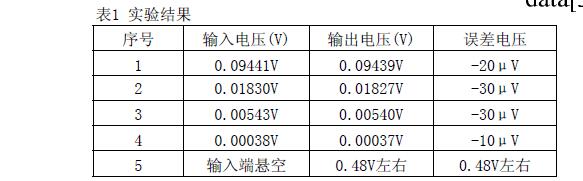
It can be seen from the above table that the error of the collected data is about minus 30 μV, which can meet the accuracy requirements of the output signal of the chromatographic Detector. When the input terminal is floating, the collected voltage is about 0.48V. This is because the input pin of the ADS1253 chip is high impedance, and the floating pin will generate an input voltage due to the current generated by the circuit board, so the chip is not used. The input channel pins should be grounded to prevent the chip from being burned out by high current input.
6 Conclusion
The chromatograph data acquisition system designed in this paper has the characteristics of high speed, high precision and high resolution. Effective anti-interference and filter design are applied in the hardware circuit to ensure the reliability of the circuit. The software is developed with C language, which reduces the difficulty of the serial-to-parallel conversion of the 24-bit conversion result by the single-chip microcomputer, and greatly shortens the development cycle. The final test results show that this data acquisition system meets the requirements of the output signal of the chromatographic Detector, and can detect more sample components. It has broad application prospects in the chromatographic instrument system.
