The touch screen is used as a human-machine interface in the gas chromatograph control system, and it can realize visual control with the cooperation of the color LCD. This system is based on S3C44B0 embedded development platform, but this processor has no SPI bus interface register, and can only simulate SPI through software to realize communication with ADS7846. The flow of touch screen data acquisition and the simulated SPI communication program implemented in C language are given in this paper.
1 Introduction
Gas chromatograph is an important class of scientific instruments among the analytical instruments with a wide range of applications and a large number. In the fields of petroleum, natural gas, fine chemical industry, metallurgy, electric power, medicine, health, grain and oil, food, environmental protection, gas, technical supervision and national defense research, it has almost become one of the analytical instruments required by modern analytical chemistry laboratories. With the popularity of gas chromatographs, customers have gradually increased their requirements for the system, not only requiring it to have good operating performance, but also to display the working status in real time and intuitively, and to require the operator to easily adjust the system's working parameters and data according to the actual situation. Acquisition, analysis, judgment and parameter display. For this reason, we have designed and developed a visual control system, which can visually display the system status, provide a fully graphical operation method, and have a low cost.
 2 Principle and system structure of gas chromatograph
 2 Principle and system structure of gas chromatograph
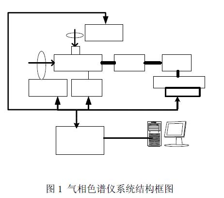
 The basic principle of chromatograph technology is (as shown in Figure 1): when a gas sample is sent into the chromatographic system through a certain sampling method, each component of the mixture in the sample is driven by the mobile phase (carrier gas) As the stationary phase of the chromatographic column, each component has different adsorption capacity in the mobile phase. When the two phases move relative to each other, each component in the sample will be repeatedly (103-106) in the two phases. The effect of various forces , so that the components in the mixture are separated, and the separated single component enters the Detector system with the carrier gas, and obtains non-electrical conversion, converting the chemical component into an electrical signal proportional to its concentration , and then analyze the sample composition through the difference of these electrical signals.
As shown in Figure 1, the control system of the gas chromatograph is mainly composed of an embedded control system (MCU), a temperature Detector, a carrier gas flow detection controller and a sample flow detection control, plus a high impedance amplifier ( With photoelectric isolator), its main feature is that the MCU is externally connected with a color LCD with a touch screen as a man-machine interface. The working principle of this system is to make the MCU send parameter setting commands to the carrier gas and sample flow controllers respectively through different contacts on the touch screen. In order to achieve reliability, this command is sent through the RS485 serial bus; after starting the detection system, The command to query the status of each Detector can be sent in real time through the touch screen. When the temperature Detector and the flow detection controller receive the command and meet their own requirements, they will also send their own status information to the MCU through the RS485 serial bus, and the MCU will receive it. After the data, the corresponding information is displayed on the color LCD, such as temperature curve, flow curve, etc.; the Detector of the chromatograph changes the detected information through a high-impedance amplifier, and then displays the detected results on the LCD to visually view the composition of the sample . At the same time, the MCU transmits the received data to the PC through the Ethernet for backup; the PC terminal can also set the parameters of the system through the MCU. In order to coordinate the communication between MCU and each detection controller, we have developed a set of internal communication protocol. The whole system is controlled through the touch screen according to the prompts on the LCD.
3 hardware implementation
We have developed an ARM7 development board (the processor is S3C44B0 with ARM7TDMI core of SAMSUNG Company, the data bit width is 32 bits, and the main frequency can reach 66MHZ) as the hardware platform for low-end embedded systems. This processor has a built-in LCD controller (supports up to 256-color STN, uses dedicated DMA); 2 asynchronous serial port controllers (supports IrDA1.0, 16-byte FIFO); provides 71 general-purpose I/Os with composite functions Port for us to connect other devices.
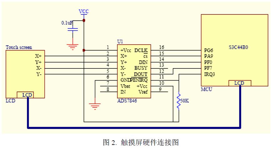
The touch screen of this system adopts AMD's resistive touch screen AMT 9502. The screen body of the resistive touch screen is a multi-layer composite film that is very compatible with the surface of the display. Conductive layer covered with an outer surface hardened, smooth, scratch-resistant plastic layer, which is coated on the inner surface with a transparent conductive layer, with many small (less than 1/1000th of an inch) transparent gaps between the two conductive layers Isolation points separate them for insulation. When the pen touches the screen, the two conductive layers are in contact at the touch point, the resistance changes, and signals are generated in the X and Y directions, and then sent to the touch screen controller to calculate the (X, Y) position.
The touch screen control chip uses TI's analog-to-digital conversion chip ADS7846, which is a typical 12-bit sampling stepwise approximation register (SAR) A/D converter. In addition to the measurement of the basic touch point position, the measurement of touch pressure can also be performed. The 2.5v reference voltage provided inside the chip can be used for auxiliary input, battery monitor and temperature measurement. Its automatic power-saving function can in turn ensure very low power consumption, which is very suitable for low-power embedded system circuits. This article only applies its basic function as a touch screen controller.
ADS7846 transmits the coordinate value to MCU through A/D, and MCU displays corresponding information on LCD after processing or sends corresponding instructions through RS485; ADS7846 can receive and execute the commands sent by MCU at the same time. ADS7846 uses SPI bus to exchange data with the outside, but S3C44B0 has no SPI bus interface, so it can only use general I/O port software to simulate SPI. The detailed hardware wiring is shown in Figure 2.
4 Software implementation
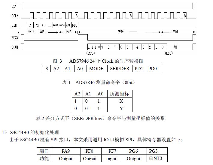
In order to obtain a coordinate value, three SPI clocks need to be transmitted between ADS7846 and MCU (see Figure 4). Send measurement command word from DIN to ADS7846 for the first time (see Table 1, see Table 2 for settings). When ADS7846 receives the first five bits of the command word, the A/D converter enters the sampling stage. After the control byte is input, after waiting for BUSY to be low, at each falling edge of DCLK, the coordinate value converted by A/D is output bit by bit from the DOUT pin to the MCU from high bit to low bit. The 12-bit A/D conversion result data is transferred at the 13th DCLK clock. Therefore, the effective data is the first 12 bits, and the last 4 bits are filled with 0.


Due to the amount of pressure and the length of time the pen is in contact with the touch screen, the contact will vibrate, which has a certain impact on the acquisition of the correct contact position value. This paper adopts the method of sampling twice to eliminate the jitter of the contact, and defines a counter count in the program to calculate the sampling times, and jump out of the sampling program after reading twice. Get the two coordinate values respectively (fisrt.x, first.y), (second.x, second.y), and then compare the difference, if it is less than a certain value, it is valid, and take the average value; otherwise judge For sampling errors, resample. Through the cooperation of touch screen and LCD, this method has achieved good practical effect, basically eliminating the influence of contact vibration.
5 summary
The procedure that this text introduces has been verified actually on S3C44B0 platform, and cooperates with color LCD, can offer the visual man-machine interface. This system is applied to the gas chromatograph workstation, the operator can visually check the operation status of the temperature Detector and the flow controller, and can modify the control parameters in real time, and the system has good stability.