Multimeters mainly include pointer multimeters (analog multimeters) and digital multimeters. The measurement principles of the two multimeters are analyzed below.
Measuring principle of analog (analog) multimeter
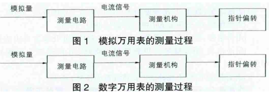
Generally speaking, the analog multimeter refers to the pointer multimeter. Its internal structure mainly includes three parts: resistance, meter head and battery. Generally speaking, the meter head is a magnetoelectric DC microampere meter. In the measurement process, if the resistance is measured, the internal battery of the multimeter will be used. The positive electrode of the battery is connected to the black test lead, so that the current will flow out from the black test lead and flow in from the red test lead. When measuring DC current, the shunt can be realized by connecting parallel resistors by shifting gears. The main reason for the shunt is that the full-bias current of the meter head is very small, so the shunt resistor is used to expand the range. When measuring DC voltage, it is necessary to connect the resistance of the meter head in series. In short, when using a pointer multimeter, the additional resistance and its range should be converted accordingly according to the difference in the measured current. Its basic measurement principle is shown in Figure 1 below.
Measuring principle of digital multimeter
The main components of a digital multimeter include: power supply and function/range switch, function converter, A/D converter, LCD display (liquid crystal display), etc. Among them, the A/D converter generally adopts the ICL7106 dual integral A/D converter. ICL7106 uses two integrations, the first integration of the input analog signal V l is called the sampling process; the second integration of the reference voltage - VEF is called the comparison process. The two integration processes are counted by a binary counter, converted into digital quantities and displayed in digital form. Its measuring principle is shown in Fig. 2 .