Overview of Digital Multimeters
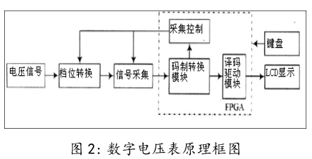
When measuring, the measured value is first converted into DC voltage through different converters, and then the voltage is measured with a digital voltmeter to obtain the measured value. Therefore, the core of the digital multimeter is a DC digital voltmeter. The measurement process of the DC digital voltmeter is to use the A/D (analog/digital) converter to convert the measured analog voltage into a corresponding digital quantity, then count through the electronic counter, and finally directly display the measured voltage value in the form of decimal numbers on the monitor.
The purpose of digital multimeter
The digital multimeter can not only measure AC and DC voltage, AC and DC current and resistance, but also measure capacitance and signal frequency, and judge whether the circuit is on or off.
The principle of digital multimeter
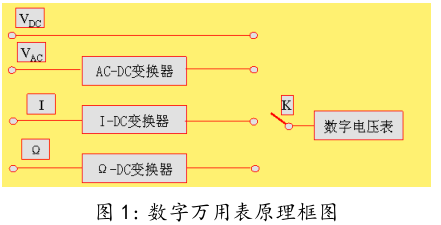
First, the measured voltage signal enters the A/D converter, and the control signal module in the FPGA sends a control signal to start the A/D converter for conversion, and the digital signal data obtained by sampling is converted into a display code in the corresponding code system conversion module . Finally, the decoding drive module sends display control and drive signals to drive the external LCD module to display the corresponding data. Through the external keyboard, you can manually reset the system and select gears. Different gears determine different voltage input ranges, and automatic conversion is realized in the program. The block diagram of the basic working principle is shown in Figure 2.