Using chemical vapor deposition technology, the catalyst substrate material was prepared by spin coating method, and the distribution state of catalyst particles was changed by controlling the angular velocity, rotation time and temperature during the substrate reduction process during the coating process, and a catalyst with uniform particle size distribution was obtained. The substrate, on which the catalyst particles are concentrated in the range of 47-62 nm, is used to grow aligned carbon nanotube arrays. The samples were characterized by scanning electron microscope, transmission electron microscope and Raman spectrometer. The results show that the flatness of the substrate prepared by the spin coating method is better than that of the common drop film method, and it is simpler and easier to control than other substrate preparation methods, and the catalyst can be uniformly dispersed. The carbon nanotube array prepared by using the substrate has good orientation.
Since the discovery of carbon nanotubes (CNTs) by Japanese scientist Iijima, it has attracted great attention from researchers for its excellent physical and chemical properties. It has broad application prospects in the preparation of high-strength composite materials and other fields. "Aligned carbon nanotubes" (ACNTs), as carbon nanotubes with the same growth direction, can give full play to the excellent thermal conductivity , thus having a wider application field . In the experimental research of inertial confinement fusion targets, the emission and utilization of epithermal electrons are the focus of physical design research. ANCTs are expected to be applied in this field .
There are many methods for preparing carbon nanotubes, such as arc discharge method, laser evaporation method and organic gas pyrolysis method, namely chemical vapor deposition (CVD). Among them, the CVD method has attracted much attention because of its simple equipment, easy scale-up to industrial scale, and strong controllability. The preparation of the catalyst substrate is extremely important in this method. How to realize the uniform distribution of the catalyst on the substrate and achieve a certain flatness has become the focus of experimental research. At present, most researchers use physical methods such as magnetron sputtering to form an extremely thin catalyst film on the substrate, and then make it into a catalyst substrate by ammonia gas etching and other methods. The substrate catalyst prepared by this method has a uniform particle size distribution and good flatness, and can grow carbon nanotube arrays with good orientation, but this method requires high equipment. In this paper, the spin coating method was used to prepare the substrate. This method has the characteristics of simple and easy to control equipment, and can make the catalyst uniformly dispersed. The catalyst substrate material that meets the requirements was prepared. Well-oriented carbon nanotube arrays.
1 experiment
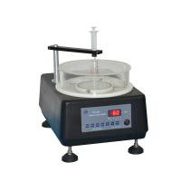
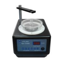
A polished quartz wafer is used as the substrate. After the quartz plate was cleaned by ultrasonic vibration, it was dried under the protection of nitrogen atmosphere. The catalyst solution is prepared by ferric nitrate, citric acid, ethanol and water in a certain proportion. A catalyst film was coated on the surface of the quartz plate using a Spin Coater (kW-4A-220 Spin Coater produced by Shanghai Kaimet Functional Ceramics Technology Co., Ltd.). The thickness and uniformity of the film are controlled by the angular speed of the spin coating machine and the time length of the high-low speed gears. The experimental device for preparing carbon nanotubes is shown in Figure 1. The system has two furnace zones, and different furnace zones can be controlled separately in the experiment. temperature. A quartz tube (length 100 cm, outer diameter 45 mm) was used as a reaction vessel, and a quartz plate was used as a reaction substrate. The prepared substrate was placed in the quartz tube, and the temperature and gas flow were adjusted to reduce the substrate and grow carbon nanotubes.
The substrate and samples were analyzed and tested by scanning electron microscope (Lecia 440, UK), transmission electron microscope (JEM-100CX, Japan, accelerating voltage 80 kV) and Raman spectrometer

Fig.1 Structural diagram of experimental device
2 Results and discussion
The surface of the reduced substrate (as shown in Figure 2) was analyzed using a scanning electron microscope, and it was found that a large number of catalyst particles were distributed on the surface of the substrate. In the experiment, the catalyst plays an important role in the growth of carbon nanotube arrays. The size of the catalyst particles determines the diameter of the carbon nanotubes, and the degree of dispersion of the catalyst determines the uniformity of the carbon nanotube arrays[12] . The adhesion between the catalyst and the substrate affects the growth mode of the carbon nanotubes (top growth mode, bottom growth mode). Therefore, it is the focus of this experiment to make the catalyst combine with the substrate with moderate adhesion and be highly uniformly dispersed. In the experiment, it is found that the catalyst film can be uniformly coated on the flat quartz glass as required by using the spin coating method, which greatly reduces the problems of uneven film thickness and surface tension caused by the drop film method.

Fig.2 SEM image and distribution of catalyst particles on the substrate surface after reduction
Figure 2 is the electron microscope picture of the substrate surface after reduction, in which Figure 2(a) is the substrate obtained by the common drop film method, it can be clearly seen from the figure that the surface of the catalyst substrate is uneven, and the dispersion is poor, and even some The catalyst coagulates into agglomerates, seriously affecting the quality of the catalyst substrate. This is mainly caused by the uneven thickness and surface tension of the base film obtained by the drop film method. Figure 2(b) is the substrate obtained by the spin coating method. Compared with Figure 2(a), the catalyst particles in Figure 2(b) are evenly distributed and have better flatness. Therefore, the spin coating method can overcome the problems of uneven film thickness and surface tension caused by the drop film method, and obtain a relatively flat substrate.
在催化剂还原过程中 ,温度的控制极为重要。当催化剂还原温度过高时 ,发现部分催化剂颗粒明显长大 ,造成粒径不均及分布不均 ;当催化剂还原温度过低时, 催化剂以外的有机成分则不容易除去 ,影响催化剂的活性及碳纳米管的生长。图2(c)和图 2(d)均为采用旋转涂膜法获得的基底, 其中图2(c)为 750 ℃下基底的还原图片 ,图中催化剂粒径分布不均匀 ,且出现了大的颗粒 ,粒径相差较大 。图 2(d)为 600 ℃下基底的还原图片 ,比较发现图中催化剂粒径分布较均匀, 且粒径相差较小 。图 2(e),(f)为图 2(c),(d)中催化剂粒径分布图, 从中可得到催化剂粒径分布的精确信息。由图 2(e)中可看出, 当催化剂的还原温度为 750 ℃时, 催化剂的粒径范围分布在 15~ 190 nm ,集中分布在 60 nm 附近, 在较大的颗粒范围中 130 和 150 nm 附近各出现了一个峰 。
总体来看 ,催化剂的粒径分布范围较宽 ,且分布较杂乱 。当还原温度降低到 600 ℃时 ,催化剂颗粒的直径则分布在 10 ~ 120 nm 范围 ,集中分布在 55 nm 附近 ,粒径范围较窄, 均匀性较好 。分析可知产生图 2(c)中现象原因主要是由于催化剂还原温度过高 ,催化剂颗粒熔融变大导致。
温度对碳纳米管的生长也有很大的影响 :温度过低导致碳源裂解过慢, 甚至无法裂解 ,同时也不利于催化剂充分表现其活性;温度过高时催化剂熔融变大, 降低活性 ,且生长的碳纳米管中杂质含量较多 。经过大量实验发现 600~ 800 ℃为很好的生长温度 。碳源气体(乙炔)与载气(氮气)的比例(体积比)不同时也会产生不同的生长效果 :当体积比过高时,反应室中碳源气体浓度过大,在高温的条件下裂解出大量碳原子 ,致使催化剂颗粒被大量碳原子包围, 中毒失去活性 ,产物中有大量无定形碳杂质生成 ;当体积比过低时,反应室中碳源气体浓度过低 ,因此碳的沉积量较少,使碳管的生长更加缓慢 , 影响其阵列效果, 甚至无法形成阵列。图 3 为相同温度(720 ℃)和压力(50 kPa),不同碳源体积分数下获得的碳纳米管。其中图 3(a)为低碳源体积分数(5%)下生长的碳纳米管 ,可发现图中碳纳米管密度较低, 且生长速度缓慢 ;图 3(b)为较高碳源体积分数(30%)下生长的碳纳米管,图 3(c)为图 3(b)的侧视图, 结合以上两图可发现该浓度下生长的碳纳米管排列较紧密 ,且密度高;图3(d)为样品的透射电镜图片 ,从图中可明显看出样品为管状结构 ,进一步证明了样品为碳纳米管, 而非纳米纤维。在实验中图 3(b)中碳纳米管的生长速度明显快于图 3(a)中碳纳米管的生长速度 ,且生长的碳纳米管较致密,阵列效果好 。但样品中有部分 Y 形碳纳米管生成, 其原因不详 。当碳源体积分数继续增高时产物中则明显出现了无定形碳杂质。

图 3 碳纳米管的电镜图像
对图 3(b)中样品进行了拉曼光谱表征, 如图 4 所示,图中峰位分别 分布在 1 344 cm-1 与 1 580 cm -1 处, 其中1 344 cm-1出现的峰为 D 峰 ,代表无序石墨中平面末端碳原子的振动;1 580 cm-1处出现的为碳纳米管的G 峰, 是由石墨的 E 2g 模式产生的, 对应于石墨层中 2 维六方晶格内sp2杂化碳原子的振动。与非晶态石墨的特征峰相比, 图中的峰位发生了明显红移, 由此可证明该样品中碳纳米管的含量较高。图中 D 峰与 G 峰的高差较大, 按照郑瑞廷等的理论同样说明该条件下制备出的碳纳米管纯净,杂质较少 。

图 4 碳纳米管的拉曼光谱图
3 结 论
本文采用旋转涂膜法制备催化剂基底,克服了滴膜法制备基底产生的薄膜厚度不均、张力不均等问题;通过对涂膜过程中角速度及旋转时间的控制,制备了符合要求的催化剂基底材料 ;利用化学气相沉积技术制备了碳纳米管阵列。分析发现 :制备的碳纳米管阵列有良好的定向性 。旋转涂膜法与其它基底制备方法相比具有对设备要求低、操作简单 、易控且能使催化剂高度均匀分散等特点 。在制备过程中 , 要求涂膜溶液中无 μm 级的杂质颗粒,否则会影响催化剂薄膜的平整性 ,在实验中常采用超精细纤维过滤膜对涂膜溶液进行过滤 。
参考文献 :
[ 1] Iijima S.Helical microtubules of graphitic carbon[ J] .Nature, 1991, 354(6):56-58.
[ 2] Bonard J M , Salvetat J P , Stockli T , et al.Field emission from carbon nanotubes:perspectives fo r applications and clues to the emissionmechanism[ J] .Appl Phys, 1999, 69(3):245-254.
[ 3] Wang H, Huan C, Dong P , et al .Controlled synthesis of aligned carbon nanotube array s on catalyst patterned silicon substrates by plasma-enhanced chemical vapor deposition[ J] .Applied Surf ace Science , 2001, 181:248-254.
[ 4] Choi K S, Cho Y S, Hong S Y , et al.Effects of ammonia on the alignment of carbon nanotubes in metal -asisted themal chemical vapor depo-sition[ J] .Jounal of the European Ceramic Society , 2001, 21:2095-2098.
[ 5] Lee C J, Son K H , Park J, et al.Low temperature growth of vertically aligned carbon nanotubes by thermal chemical vapor deposition[ J] .Chem Phys Lett , 2001, 338:113-117.
[ 6] Lee C J, Park J, Huh Y, et al.Temperature effect on the growth of carbon nanotubes using themal chemical vapor deposition[ J] .ChemPhys Lett , 2001, 343:33-38.
[ 7] Jung M J , Eun K Y , Baik Y, et al.Effect of NH 3 environmental gas on the growth of aligned carbon nanotube in catalystically py rolizingC 2 H 2 [ J] .Thin Solid Films , 2001, 398-399:150-155.
[ 8] Ebbesen T W , Ajayan P M .Large-scale synthesis of carbon nanotubes[ J] .Nature, 1992, 358:220-222.
[ 9] Guo T , Nikolaev P , Thess A , et al.Catalytic g rowth of single walled nanotubes by laser vaporization[ J] .Chem Phys Lett , 1995, 243:49-54.
[ 10] Ivanov V , Nagy J B, Lambin P .The study of carbon nanotubules produced by catalytic method[ J] .Chem Phys Lett , 1994, 223:329-335.
[ 11] Liu H P, Cheng G A , Zhao Y .Controlled growth of Fe catalyst film for sy nthesis of vertically aligned carbon nanotubes by glancing angledeposition[ J] .Surf ace and Coatings Technology , 2006, 201:938-942.
[12] Ci Lijie, Wei Bingqing, Liang Ji. Preparation of carbon nanotubes [J]. New Carbon Materials, 1998, 13(2):65-71. (Ci LJ, Wei BQ, Liang J, et al.Preparation of carbon nano-tubes. New Carbon Materials, 1998, 13(2):65-71)
[ 13] Deng WQ , Xu X, Goddard WA , et al.A two-stage mechanism of bimetallic catalytic zed g rowth of single-walled carbon nanotubes[J].NanoLett, 2004, 4:2331-2335.
[14] Amelinckx S, Zhang XB, Bernaerts D, et al.A formation mechanism for catalytically grown helix-shaped g raphite nanotubes[J].Science,1994, 265:635-639.
[15] Zheng Ruiting, Cheng Guoan, Zhao Yong. Comparative Study on Raman Spectroscopy of Carbon Nanotube Arrays[J]. Spectroscopy and Spectral Analysis, 2006, 26(6):1071-1075.(Zheng RT , Chen GA , ZhaoY. A comparative Raman study of carbon nanotubes array s. Spectroscopy and Special Analysis sis , 2006, 26(6):1071-1075)