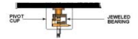
The operator must exercise caution when installing or removing the rotor. All Brookfield instruments can measure very small torques caused by the rotation of the rotor in the sample 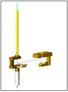 fluid . This requires that friction be kept to a minimum. Brookfield has almost no friction through the support system composed of pivot point (PIVOT POINT) and jewel bearing system (JEWELED BEARING), as shown in the right picture. This support mechanism is inside the pivot cup (PIVOT CUP), just above where the rotor is mounted , as shown in the picture below.
When installing or unloading the rotor, any downward force or lateral movement will cause a lot of wear and tear on this support system.
When you tighten or loosen the rotor, the correct way to install and unload the rotor is to slightly lift the nut where the rotor is installed, and then lift it up firmly. Also remember: the rotor is attached from the opposite direction of the threads (left hand direction). If you are using
When you tighten or loosen the rotor, the correct way to install and unload the rotor is to slightly lift the nut where the rotor is installed, and then lift it up firmly. Also remember: the rotor is attached from the opposite direction of the threads (left hand direction). If you are using a Wells-Brookfield cone and plate instrument, be sure to use the wrench provided by Brookfield when installing and removing the cone rotor, and carefully turn the nut where the rotor is installed upwards. Using the wrench provided, carefully screw up the nut where the rotor is installed.

Precautions such as those described above will ensure long-term reliable service of your Brookfield Viscometer or Rheometer. In addition, the previously recommended annual calibration of the stone's support and pivot points has become part of the calibration service.
For a quick check to determine the condition of your instrument's pivot point and stone support system, you can follow these steps:
1. When the rotor is not installed, turn on the power and observe whether the display of the instrument returns to zero automatically;
2. Select the display mode according to the model of the instrument, key in some values appropriately, and you can see the torque percentage ;
3. Observe whether the value of the torque percentage is within –0.1% to +0.1%;
4. Start the motor to make the speed reach 10rpm or 12rpm;
5. When the motor starts to turn, the torque percentage reading fluctuates. Within a few seconds, the torque percentage will stabilize and the value should still be displayed within –0.1% to +0.1%;
6. Next, stop the motor. When the torque percentage stabilizes, its value should still be within -0.1% to +0.1% ; if the torque percentage is not within this range, it means that the support system of the instrument has been damaged to a certain extent. Continue to repeat the calibration steps, if the calibration check falls outside the allowable range, you can contact your local Brookfield office or directly to Brookfield, tell your results and get service for your instrument.