This article introduces methods that allow users to go a step further to measure accurate viscosity. At the same time, it introduces the composition and principle of the digital viscometer produced by Shanghai Nirun Intelligent Technology Co., Ltd., and provides some useful operation skills. Professionals who specialize in viscosity measurement may not need to read these materials again, but for general users, they should read before using digital viscometers. An integral base facilitates accurate viscosity measurements.
How a digital viscometer works
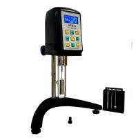
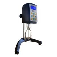
The digital viscometer produced by Shanghai Nirun Intelligent Technology Co., Ltd. can adjust different speeds. Its biggest advantage is that it uses a stepping motor instead of gear transmission. It makes the digital viscometer rotate more smoothly, and the speed can be continuously variable in a wide range.
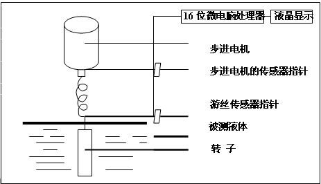
As shown in the figure, the stepper motor is driven with high resolution to drive the pointer of the sensor, and the rotor is driven to rotate through the hairspring and the rotating shaft. If the rotor is not resisted by the liquid, the hairspring sensor pointer is in the same position as the stepper motor sensor pointer. On the contrary, if the rotor is subjected to the viscous resistance of the liquid, the torque sensor will generate torque to compete with the viscous resistance, and finally reach a balance. At this time, the output signal of the photoelectric sensor is sent to the 16-bit microcomputer processor for data processing, and finally the viscosity value (mPa·s) of the liquid is displayed on the LCD screen with night vision function.
Viscosity, viscous force, and flow resistance (related to the tightness of the torque sensor) are related to the speed of the rotor and the shape of the rotor. When the speed increases or the rotor increases, the viscous force will increase. Therefore, when the speed increases or the rotor becomes larger, it can be read by the deviation of the torque sensor. The smallest range of viscosities can be measured with the largest surface area spindle at the highest speed; and the largest range of viscosities can be measured with the smallest surface area and slowest speed. The rheological properties of the fluid can be measured with the same rotor at different speeds.
Viscosity Measurement Tips
Like many precision instruments, proper operation helps to increase the efficiency of the digital viscometer. The introduction of each operation step can be found in the operation manual of each unit in the instruction manual, and this section does not repeat these parts. This section will provide some suggestions and guidelines, and through these complete basic instructions, many accurate measurements can be further completed.
record keeping
During the viscosity measurement procedure, we recommend that data recording is required. This includes digital viscometer model, rotor model (including accessories), speed, percent torque, sample tank size, whether to use a protective frame, etc. We recommend making yourself a record sheet that accompanies the viscosity measurement.
Rotor and protective frame
Each spindle needs to be inspected before use. If the spindle has corroded or changed shape, the measured viscosity will be incorrect. When you find that the new rotor is defective or damaged in shape, please contact us to get a new rotor. If you need to use it in a special environment, we have 316L series stainless steel for you to choose from. In addition, rotors in special materials can also be ordered.
When installing the rotor, please pay attention to the left helical direction to lock it correctly. To avoid damage to the bearings, lift the rotor coupling slightly when installing the rotor. When the rotor is installed, please do not hit the inner wall of the container, so as not to damage the alignment of the bearing. Before installing the rotor into the digital viscometer, it is necessary to place the rotor correctly in the sample. The protective frame of the rotor can protect the rotor from hazards and define the fluid boundary conditions. In addition, when using No. 1 or No. 2 rotor , also has a great influence on the correction. This protective frame needs to be used at all times, if the situation does not allow the use of a tripod, it needs to be noted in the results. Then it is necessary to do another blank experiment to correct the error of the data.
Select the speed of the rotor
Using an appropriate rotor and speed, it is possible to get a correct viscosity pattern. At the beginning of viscosity testing, the best way to choose the spindle and speed is the trial and error method, adjust the viscometer scale to 20 to 90, when the percentage scale is within this range, the accuracy will be measured can improve. If the percentile scale exceeds 90, select a slower speed or smaller rotor. Conversely, if the percentile scale is less than 20, select a higher RPM or larger rotor.
For example, the maximum measuring range of No. 1 rotor of DV-2+PRO digital viscometer is 100mPa.s at 60RPM. The maximum measurement range is 90 mPa.s, and the minimum range is 20 mPa.s. If the viscosity of the sample is 150 mPa.s, an additional rotor speed combination % needs to be selected to fit within the measurable range, however, if the sample is around 50 mPa.s, this combination is quite suitable. After such preparations, the rotor and rotational speed of the application can be properly selected. When measuring multiple sets of viscosity data, it is also necessary to do the same action to select the appropriate rotor and speed. When it is necessary to experiment at different speeds. Please select a set of rotors that can fit the entire measuring range.
Sample tank size
We recommend that when measuring viscosity, the size of the sample cell is preferably 70mm or larger in inner diameter. Usually a 400 ml beaker container is used. Using a smaller beaker will result in higher viscosity, especially when using spindles 1 and 2. When using a smaller sample cell, it is easy to note this in the results and ignore possible calibration errors. The correlation between these data is correct as long as the same sample well is used throughout.
sample status
Fluid samples need to avoid air bubbles in them, which can be solved by tapping the sample well or using a vacuum device. The sample needs to be maintained at a constant and uniform temperature, which can be determined by examining different areas of the sample well. Note that the sample, rotor and protective frame need to reach the predetermined temperature before reading the data. A uniform temperature distribution is achieved by stirring before reading the data, but it needs to be confirmed that such stirring will not affect the viscosity of the sample. We can use a special viscosity measuring constant temperature Water Tank to make the system temperature meet the requirements. Please contact us for the selection of a special viscosity measuring constant temperature Water Tank. Operation at high temperature (over 100°C) requires the use of heater accessories, and the uniformity of the sample is also an important factor, especially in some dispersed systems where sedimentation may occur. In some cases, simple agitation prior to measuring data can prevent the system from settling.
Immersion condition of the rotor
The spindle needs to be immersed in the sample up to the mark, an incorrect position will result in incorrect viscosity data. In some cases, the sample changes its rheological state due to immersion in the rotor. In order to avoid this situation, we recommend to enter the rotor measurement at different positions of the sample, and then move horizontally to the center of the sample chamber. This action needs to be done before .
read data
Before operating the viscometer, it is necessary to make sure that the viscometer is securely fixed on the table and at the proper height. Select the combination of rotor and rotational speed, and install it on the viscometer. Activate the viscometer and allow it to reach a stable reading. However, the momentum gained during the acceleration of the rotor may cause the reading to oscillate around the stable reading. There are several ways to obtain more satisfactory data. In some cases, it may take up to 5 minutes to stabilize. Under normal conditions, you just need to wait a reasonable amount of time for the reading to stabilize. A more reproducible method is to allow the rotor to rotate for a certain number of cycles before reading the data. Since the situation is different for different speeds, another feasible method is to read the data when the rotor rotates for a certain period of time. You may find that the reading does not appear steady but keeps jumping. This is often due to the non-Newtonian nature of the fluid. But if the reading continues to increase or decrease, the properties of the fluid may have changed over time, in which case additional skill is required to obtain the correct viscosity. The torque display of the digital viscometer may still have a 0.1% or 0.3% runout even after steady state is achieved. In this case, just read the averaged data. Larger jumps may be caused by other reasons.
Correction
We are often very concerned about the accuracy of viscometers. Here are some tests that can help us understand the condition of a viscometer:
(A) Damage to the bearings can also cause incorrect and less reproducible viscometer readings. Alternate testing of the following methods can help you assess the condition of these mechanisms:
1. For digital viscometers, the power should be turned on, but the motor should be turned off.
2. Turn the rotor connector 15 degrees and release to allow it to rotate automatically.
3. If it can rotate smoothly every time, it means that there is no problem with the bearing. Press the measure button, the viscosity value should be 0 mPa.s If the connector turns slowly or unevenly, it means that the viscometer is not working well and needs to be repaired.
(B) Finally the viscometer can be calibrated using standard viscosity samples. Carefully measure these standard viscosity samples according to the operating manual. The standard viscosity sample (error range within ±1\%) provided by Nirun Company is a very satisfactory choice. Due to the possibility of unpredictable fluid behavior, we do not recommend using other fluids for calibration.
(C If the viscometer can pass all the above tests, then the performance of the viscometer should be satisfactory. If you still feel that the measured data is unreasonable, please contact our Nirun company.
Recalibrating the Digital Viscometer
在许多环境下,使用尼润公司粘度计测量粘度时,并无法使用 400 ml 烧杯容器。如果移动这些流体是十分麻烦或很浪费时间,就会有需求要使用不一样的容器。有些时候,为了避免做额外的清理,我们还会不使用保护框架。
以上这些状况都需要重新校正粘度计已获得准确的粘度数据。
如果你测量了一组粘度, 而只想测量同样的样品在不同环境下的粘度, 只需做以下的步骤即可:
(1.) 将样品放于同一个样品槽中, 并且同样使用脚架或不使用脚架。 注意需使用同样的转子与转速,并且保持在同样的温度。
(2.) 记下新的读数, 做为新的参考点。
当粘度计是用来做品质控制时, 这个步骤可以建立控制的方法, 操作者此时并不需要知道样品真正的粘度。
如果你需要样品真正的粘度又不想使用脚架, 可以遵循下列步骤:
(1) According to刚开始介绍的操作步骤, 测量牛顿流体的粘度, 并使用标准样品槽。我们强烈建议此时使用尼润公司提供标准粘度样品。 小心操作测量步骤, 因为最后的结果与此息息相关。显示读数即可得到流体的粘度(mPa.s)。
(2) 将此标准粘度样品置入你所想要使用的样品槽内。 注意温度需要保持一致。
(3) 标准粘度样品使用后,试将使用的转子, 在这个新的样品槽内重新测量粘度。
例如,在印刷墨中添加溶质会使墨水的粘度值变小;而且添加的溶质种类可用来控制油漆的流变性质。
数字式粘度计的保养
上海尼润智能科技有限公司生产的数字式粘度计拥有高度的可靠性,且能提供给仪器正确的操作指令。为了避免发生潜在的问题,一些操作要点值得使用者记得:
(A) 粘度计对于外在环境的调整适应能力是极小的;仪器的很好的表现需要建构在免除所有可能影响仪器灵敏度的不必要的摩擦力。此意需要有良好的清洁习惯。注意要避免灰尘、烟、液体和其它形式的污染源进入粘度计中。如果需要在污染的环境下操作仪器,我们建议使用延长的转子和/或清洁用具来减少污染物进入系统中。
(B)不要将已有流体附着的转子装设在仪器上。
(C) Do not expose the viscometer to an environment of 75°C. When it is necessary to measure the viscosity of samples at high temperature, it is recommended to use the extended spindle or the attached heating accessories.
(D) Avoid inserting and squeezing the rotor joint from the side or below, because the joint can protect the rotor's center and bearings, and such rough actions will damage or make the joint insensitive. Always remember to lift the rotor joint when accessing or removing the rotor. Do not knock the rotor into the sample well or damage the sample well, and do not pull directly on the rotor or the rotor connector.
(E) Do not drop the instrument or shake it violently. The base of the digital viscometer provides convenient and sturdy support. If it is necessary to carry the viscometer to other places for use, it must be kept in a box when not in use.
If the viscometer is physically damaged, please send the instrument to the after-sales service department of Nirun Company for repair, or contact the agent who purchased the instrument for assistance.
The maintenance of the instrument has different time according to different use conditions; if it is in normal use condition, once a year service is enough to keep the instrument in good operating condition; more severe operating environment requires more frequent maintenance . For this service, please call Nirun or the agent of the instrument.
Find problems and fix faults
A product manual is attached to the viscometer, which describes in detail how to use the instrument and precautions. The following lists some common problems encountered when using the viscometer, and attaches the possible causes and suggested repair methods.
The rotor cannot turn
□ Make sure the viscometer is plugged in.
□ Check the voltage used by the viscometer (115V, 220V): it needs to match the voltage on the wall socket.
□ Make sure the power switch is in the ON position.
□ Make sure the speed setting is correct and at the speed you set.
When the rotor turns, the rotor shakes or the trajectory of the rotor appears to bend
□ Make sure the rotor is tight on the rotor joint.
□ Check that the rotor is straight; if it is bent, replace it.
□ Check whether there is dust in the joint area of the viscometer joint and the rotor joint and the thread; the thread on the joint is in place to remove it.
□ Check the threads for abrasive wear; if the threads are worn, have the device repaired.
□ Check if the rotors are not rotating in the same circle or vibrating. When measuring the horizontal movement distance of the rotor in the air from the bottom of the rotor, we allow a deviation of 0.5mm.
□ Check whether the viscometer joint is bent; if so, the device needs to be repaired. If the error of the equipment is out of range, the instrument needs to be sent for repair.