Thin layers of materials are widely used in aerospace, oil and gas transportation, automobile manufacturing and biomedical engineering and many other fields, such as material surface protective coatings, composite structural cementing layers, rare metal foil materials and heart valves, etc., and occupy an increasingly important position in the field of engineering technology. Among a series of performance indexes to characterize the quality of thin layers, the thickness of the thin layer of materials is not only a parameter to characterize the geometric size of the thin layer itself, but also has a great impact on the performance and life of the thin layer, so it has become one of the parameters of great importance in the evaluation of thin layer quality. In addition to the advantages of non-destructive and 100% detection, ultrasonic testing technology has also become an important direction of nondestructive testing of thin layer thickness of materials because of its good directionality, strong penetration ability, high energy and harmlessness to the human body. Here are four ways that ultrasonic Thickness Gauges measure thin layers of material.
Pulse-echo Thickness Gauge
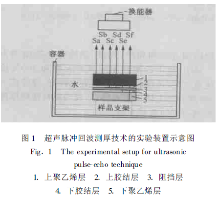
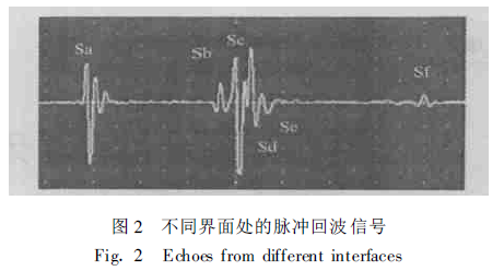
The principle of Pulse-Echo thickness measurement is mainly to measure the propagation time of the ultrasonic pulse in the sample, and then calculate the thickness of the specimen according to the propagation speed of the ultrasonic pulse in the sample. The experimental setup of pulse-echo thickness measurement is shown in Figure 1. The ultrasonic transducer in the figure generates a pulse wave of a certain frequency that is incident perpendicular to the surface of the specimen. When the incident wave propagates in different media, the reflected wave will be generated at the interface of the adjacent two media, and the reflected wave at the interface from medium 1 to medium 5 is recorded as Sa, Sb, Sc, Sd, Se and Sf in order (see Fig. 1), and the echo signal received by the ultrasonic transducer is shown in Fig. 2. If the velocity v of the specimen is known, the thickness h of the corresponding dielectric layer can be calculated using the time interval Δτ between adjacent pulse-echoes.
Pulse-echo thickness measurement is mainly used to measure the thickness of metallic and non-metallic materials (such as plastics, glass, and ceramics) with fine-grained structures, and is not suitable for the thickness measurement of coarse-grained materials and composite materials. Unlike other ultrasonic thickness measurement methods, the pulse-echo method is not limited by the geometry of the material to be measured, and can measure the thickness of the curved material in addition to the thickness of the flat material. Maev et al. [10] used a broadband transducer (center frequency of 15 MHz and 20 MHz, respectively) to focus the veins using water immersion
The thickness measurement of multi-layer bent polymer (0.130 ~2.033mm) is realized by the flush return method, and the measurement error can be as small as 0.6%. The disadvantages of the pulse-echo method are: (1) When the thickness of the thin layer is less than twice the wavelength, the reflected echoes on the upper and lower surfaces of the tested sample will be mixed together and cannot be distinguished, resulting in the failure to achieve the thickness measurement of the thin layer; (2) The accuracy of thickness measurement is greatly affected by the acoustic attenuation and surface roughness of the material. However, the pulse-echo method is still widely used because of its low cost, simplicity, and high accuracy in measuring the thickness of materials above 1 mm.
Time domain reflection field analysis Thickness Gauge
In the traditional ultrasonic thickness measurement method (pulse-echo method), when h/λ<2 (h is the thickness of the sample to be measured, λ is the ultrasonic wavelength), a large number of signals reflected from the upper and lower surfaces of the sample to be tested will produce aliasing [11]. It is difficult to distinguish these signals by using the ultrasonic pulse-echo method, so the Time-Domain Reflection Field Analysis (Time-Domain Reflection Field Analysis) thickness measurement method is proposed. The geometric model of the time-domain reflection field analysis thickness measurement method is shown in Figure 3, where S 0 represents two thin layers with the same acoustic properties, and S represents the sample to be tested, with a thickness of h.
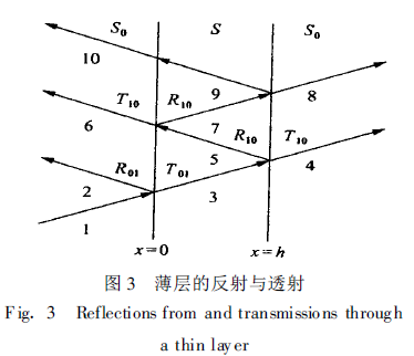
In the experiment, the sum gr (t + s0 x) of the incident wave f (t -s0 x) and the reflected wave of the acoustic field is obtained firstly.
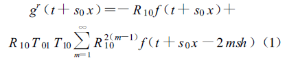
where s ——— the slowness of ultrasound propagation in the sample medium to be tested
Tij ——— the transmission coefficient of ultrasonic waves from medium i to medium j
RIJ ——— the reflection system of ultrasound waves at the interface of the medium i and jnumber
Let ξ=t +s0 x , after a series of derivations
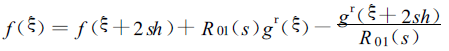
According to the polynomial on the right side of Eq. (2), the calculated value f(ξ) can be obtained, and then the root mean square deviation of the calculated value f (ξ) and the experimentally measured value f*(ξ) can be obtained
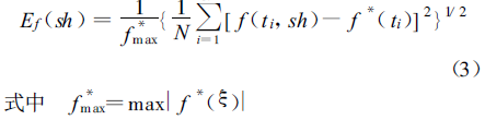
N —The total number of detection points
The velocity of sound is known, and the minimum deviation is found to determine the thickness of the specimen to be tested. In the experiment, transducers with center frequencies of 1MHz, 2.25MHz and 5MHz were used to detect the water layer with an actual thickness of 0.24mm, and the measurement results are shown in Fig. 4.
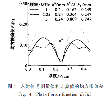
The time-domain reflection field analysis method is an improved time-domain thickness measurement method, which makes up for the shortcomings of the pulse-echo thickness measurement method and improves the accuracy of thickness measurement. Zhu Changyi et al. [12] used a 1MHz transducer to measure the thickness of aluminum plate (0.089 ~12.675mm) using a 1MHz transducer, and the error could be less than 1 %. Byoung-Geuk Kim et al. [11] used the time-domain reflection field analysis method to measure the thickness of a 0.06 ~ 1 .44 mm thick water layer (0 .04 <h/ λ<5, sandwiched between two parallel aluminum plates), and the thickness measurement accuracy increased with the increase of transducer frequency or h/λ.
Lambbofa
Lamb waves are elastic waves propagating in an infinitely large plate-like medium, which can be divided into two types: symmetrical Lamb wave (S type) and antisymmetric Lamb wave (A type) according to its different vibration forms in the plate.
The Lamb wave thickness measurement method mainly uses the dispersion characteristics and multi-mode characteristics of the Lamb wave [7] to excite a certain frequency of Lamb wave in the sample to be tested and receive it by the ultrasonic transducer, and then perform a two-dimensional Fourier transform [7, 13] (2-D FFT) on the received signal or obtain the dispersion curve of the Lamb wave according to the propagation dispersion equation of the Lamb wave [7, 13], and then compare it with the theoretical dispersion curve to realize the pattern recognition of the Lamb wave.
When the Lamb wave propagates in a thin plate (λ h) with a thickness of 2h, there is for the zero-order antisymmetric mode A0
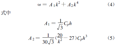
where ω ——— angular frequency
k ——— wavenumber, and k = v L/ v T
Cp ——— phase velocity
h ——— half the thickness of the specimen
For zero-order symmetric mode S 0, there is ω/k =Cp =2vT(1- 1k2) (6)
The propagation velocity of the Lamb wave in the thin layer can be approximated by CP, which can be obtained directly from the experimental results in S0 mode using the 2-D FFT or by solving the dispersion equation of the Lamb wave. A1 and A2 can be obtained by fitting the experimental results of equation (4) or equation (5) and A0 mode. Knowing A1, A2 and CP, you can find the thickness of the thin layer to be measured
At present, Lamb wave thickness measurement has become one of the hot spots in ultrasonic research at home and abroad, which is mainly used to measure the thickness of solid material sheets, and is not suitable for thickness measurement of coatings or thin films, and can measure the thickness of coarse-grained materials and composite materials. Eduardo Moreno et al. [14, 15] used the Lamb wave method to measure the thickness of the thin composite layer (2.05 ~9.80mm). Gao Weimin et al. [13] used the laser-excited Lamb wave method to detect the thin layer of pure metal copper (283 μm), and the minimum error of thickness measurement was 0 .54 %. Since the Lamb wave Thickness Gauge is performed on one side of a thin layer, it is more suitable for container and trough inspection environments.
Surface wave method
Surface waves are waves that propagate on a free solid surface bounded by a vacuum or gas. When propagating on the surface of a solid material with a thickness of h, the surface wave velocity is usually close to but less than the velocity of the bulk wave in the medium where the interface is formed, and its sound velocity is related to the Young's modulus E, Poisson's ratio ν and density ρ of the material, and its mathematical expression is as follows
The energy of the surface wave propagating in the solid medium is only concentrated in a small area of the surface of the material, and the vibration amplitude changes exponentially along the depth direction, and the attenuation is very fast with the increase of depth, and the amplitude is very weak at more than one wavelength from the surface, so that it has a high sensitivity to the film or coating, and the propagation speed is affected by the film or coating material. The equation for the propagation of surface waves in thin films and matrix materials is
c(ω)=ω/k=c(E,E′,ν,ν′,π,ρ′,d/λ)(9)
where ω=2πf (angular frequency)
k=2π/λ (wave vector)
E——— Young's modulus of thin film materials
ν——— Poisson's ratio of the film material
ρ——— density of the film material
d——— thickness of the film material
E'——— Young's modulus of the matrix material
ν'——— Poisson's ratio of the matrix material
ρ'——— density of the matrix material
At the interface between the film and the matrix material, the strain and displacement of the surface wave are continuous. According to the boundary conditions and the Navier′s equation for the propagation displacement of the surface wave, a linear system consisting of six equations can be obtained. When the determinant of the linear system is zero, the relation between ω and k (9) can be deduced, and the theoretical sound velocity curve of the surface wave can be obtained. In the process of measuring the thickness of thin layers by using the surface wave method, a laser is usually used to excite a high-frequency surface wave, and the propagation signal of the surface wave at different distances between the laser source and the transducer on the surface of the sample to be tested is received by the transducer. Then, the FFT transformation of the received signal is performed to obtain the actual sound velocity curve of the surface wave, and then the thickness of the sample to be tested can be obtained by comparing it with the theoretical sound velocity curve. The surface wave method is an ultrasonic thickness measurement method with high measurement accuracy, which can realize the thickness measurement of thin layers from a few microns to hundreds of microns, and is less affected by the surface roughness and shape of the material, especially suitable for the thickness measurement of thin films and coating materials, and can also be used to measure the thickness of cemented layered materials. Fereydoun Lakestani et al. have used the surface wave method to measure the thickness of plasma sprayed metal (NiCoAlY) coatings (190~330μm). Schneider et al. [3~5] in Germany used the surface wave method to measure the thickness of TiN thin films (1.45~2 μm). WuT-T et al. and Flannery successively measured the thickness of the cemented layer and aerogel film using the laser-excited surface wave method.
These are the four measurement methods of ultrasonic Thickness Gauges.