The main purpose of coating thickness measurement is to control costs while ensuring adequate coverage.

The method used in a particular case is usually determined by the type of coating and substrate, the thickness range of the coating, the size and shape of the part, and the economy.

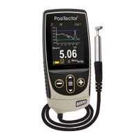
Figure 1: Pencil magnetic peel Thickness Gauge. Source: DeFelsko

Fig. 2. Rotary dial magnetic pull-off Thickness Gauge.
Various accepted methods can be used to determine the thickness of an organic coating. The method used in a particular case is usually determined by the type of coating and substrate, the thickness range of the coating, the size and shape of the part, and the economy. Commonly used measurement techniques are non-destructive dry membrane methods such as magnetic, eddy current, ultrasonic, or micron measurements; Destructive dry film methods such as cross-sectional or gravimetric (mass) measurements; and wet film measurements.
magnetism
Magnetic thin-film meters are used to non-destructively measure the thickness of non-magnetic coatings on ferrous substrates. This method measures most coatings on steel. Testing with a magnetic Tester is sensitive to surface roughness, curvature, substrate thickness, and substrate composition. Magnetic measuring instruments use one of two operating principles: magnetic pull-off or magnetic/electromagnetic induction.
Tech tipsThickness standards come from many sources, but it's better to make sure they're traceable to a national measurement agency, such as NIST. Periodic inspections are carried out according to these standards to confirm that the gage is operating properly. When the readings do not meet the accuracy specifications of the gage, the gage needs to be adjusted or repaired and then calibrated again. |
Magnetic pull-off
These gages use permanent magnets, calibration springs, and scales. The attraction between the magnet and the ferromagnetic substrate pulls the two together. As the coating thickness that separates the two coats increases, it becomes easier to pull the magnet apart. The coating thickness is determined by measuring this pull-out force – the weaker the force, the thicker the coating.
Usually supplied in the form of pencil or rotary dials, the magnetic pull-out gauge is sturdy, simple, inexpensive, portable, and usually does not require calibration adjustments. They are the tool of choice when fewer daily readings are required.
The pencil-type model uses a magnet mounted on a coil spring perpendicular to the coated surface. Most pencil pull gauges have large magnets and are designed to work only in one or two positions, which partially compensates for gravity. A more accurate version is available with a small, accurate magnet for measurements on small, hot or hard-to-reach surfaces. When the gage is pointing down, up, or horizontally, the triple indicator ensures accurate measurements with an error of ±10%.
Rollback dials are common magnetic pull gages. A magnet is attached to one end of a pivoting balance arm and connected to a calibrated hairspring. By rotating the dial with your fingers, the spring increases the force on the magnet and pulls it off the surface. These gages are easy to use and have a balanced arm that allows them to work in any position, regardless of gravity. They are safe in explosive atmospheres and are commonly used by paint contractors and small powder coating operations. The typical tolerance is ±5%.
Magnetic and electromagnetic induction
Magnetic induction instruments use permanent magnets as a source of magnetic field. Hall-effect generators, or magnetoresistances, are used to sense the magnetic flux density at the poles of a magnet. Electromagnetic induction instruments use alternating magnetic fields. A soft ferromagnetic rod wound with a thin wire is used to create a magnetic field. The second coil coil is used to detect changes in magnetic flux.
These electronic instruments measure changes in magnetic flux density on the surface of a ferromagnetic substance near the surface of a magnetic probe. The magnitude of the flux density at the probe surface is inversely proportional to the distance from the substrate. The coating thickness can be determined by measuring the flux density. The typical tolerance is ±1%.
Electronic magnetometers come in a variety of shapes and sizes. They typically use constant pressure probes to provide consistent readings that are not affected by different operators. The readings are usually displayed on a liquid crystal display (LCD). Some electronic meters offer additional utility by accepting interchangeable probes for applications related to coating applications: properties for sandblasting to clean surfaces, monitoring and recording environmental conditions, measuring the effects of corrosion on substrates, etc.
In contrast to magnetically drawn instruments, most electronic meters have the option of storing the measurement results, performing instant analysis of the readings, and outputting the results to a computer for further examination through a variety of software solutions. Typically provided by gage manufacturers, the reporting and analysis software used to store thickness readings can be installed on a computer or accessed via the internet (cloud-based). Recent hardware and software innovations have enabled measurement operators to directly integrate their smart devices (mobile phones, tablets, etc.) with coating thickness measurement, analysis, and reporting processes.
The gage manufacturer's instructions should be followed carefully to obtain accurate measurements. Standard test methods are available in ASTM D7091, ISO 2178, and SSPC-PA 2.
eddy
Eddy current technology is used to non-destructively measure the thickness of non-conductive coatings on non-ferrous metal substrates. A thin coil that conducts high-frequency alternating current (above 1 MHz) is used to set an alternating magnetic field on the surface of the instrument probe. When the probe is close to a conductive surface, the alternating magnetic field creates eddy currents on the surface. The substrate properties and the distance of the probe from the substrate (coating thickness) affect the size of the eddy current. Eddy currents generate an inverse electromagnetic field that can be sensed by the excitation coil or a second adjacent coil.
Eddy current coating Thickness Gauges look and operate similarly to electronic magnetometers in that they typically use a constant pressure probe and display the results on an LCD. They also have the option to store measurements or perform instant analysis of readings and output them to a printer or computer for further examination. The typical tolerance is ±1%. The test is sensitive to surface roughness, curvature, substrate thickness, type of metal substrate and distance from the edge.
ASTM B244, ASTM D7091, and ISO 2360 provide a standard method for the application and performance of this test.
It is now common to combine the principles of magnetism and eddy currents into a single unit. Some simplify the task of measuring most coatings on any metal, by automatically switching from one principle of operation to another, depending on the substrate. These combinations are popular with painters and powder coaters.
ultrasonic
Ultrasonic Pulse Echo Technology of Ultrasonic Thickness Gauges is used to measure the thickness of coatings on non-metallic substrates (plastics, wood, etc.) without damaging the coating.
The instrument's probe contains an ultrasonic sensor that sends a pulse through the coating. The pulses are reflected back from the substrate back to the sensor and converted into high-frequency electrical signals. The echo waveform is digitized and analyzed to determine the coating thickness. In some cases, individual layers in a multilayer system can be measured.
The typical tolerance for this device is ±3%. ASTM D6132 and ISO 2808 provide a standard method for the application and performance of this test.
micrometer
Micrometers are sometimes used to check the thickness of coatings. They have the advantage of measuring any coating/substrate combination, but have the disadvantage of needing access to bare substrates. The requirements for touching the surface of the coating and the underside of the substrate can be restrictive, and they are often not sensitive enough to measure thin coatings.
Two measurements are required: one with the coating and the other without. The difference between the two readings, the height varies, is considered the coating thickness. On rough surfaces, microns measure the coating thickness above the highest peak.
to cross-sections
A destructive technique is to cut the coated portion in a cross-section and measure the film thickness by looking at the incision with a microscope. It can also be determined by making a geometrically designed incision on the dry film coating and looking at the cross-section with a zoom microscope. A special cutting tool is used to create a small but accurate V-groove on the coating and into the substrate. Gages can be used to complete cutting techniques and illuminate zoom magnifiers.
While the principle of this destructive method is easy to understand, there is a chance of measurement error. It takes skill to prepare the sample and interpret the results. Adjusting the measurement reticle to a jagged or fuzzy interface can cause inaccuracies, especially between different operators. This method is used when non-destructive methods that are not cheap are not feasible, or as a way to confirm non-destructive results. ASTM D4138 outlines the standard method for such a measurement system.
GRAVIMETRIC
By measuring the mass and area of the coating, the thickness can be determined. The simple way to do this is to weigh the part before and after coating. Once the mass and area have been determined, the thickness can be calculated using the following formula:

where T is the thickness in microns, m is the coating quality in milligrams, A is the area tested in square centimeters, and d is the density in cubic centimeters.
When the substrate is rough or the coating is uneven, it is difficult to relate the quality of the coating to the thickness. Laboratories are well suited to handle this time-consuming and often destructive method.
Measure before drying
A wet Film Thickness Gauge helps determine how much material needs to be applied to achieve the specified dry film thickness at a specified dry film thickness, provided that the solid volume percentage is known. They measure all types of wet organic coatings, such as paints, varnishes, and varnishes on flat or curved smooth surfaces.
Measuring the wet film thickness during use indicates that it needs to be corrected immediately and adjusted via the applicator. Correcting membranes after drying or chemical curing requires expensive additional labor time, can lead to membrane contamination, and can cause problems with the adhesion and integrity of the coating system.
The equation used to determine the correct wet film thickness (WFT) with and without diluent is as follows:
No Diluent:

Four types of gauges were used, including notches, lenses, eccentric rollers, and needle micrometers. Everyone has their own operating procedures. Grooving meters, also known as stepped or comb gauges, are common.
Slot strain gauges should be used on smooth surfaces, there are no irregularities, and they should be positioned along the length of the surface rather than its width. The use of a wet film gauge on a fast-drying coating can produce inaccurate measurement results. ASTM D4414 outlines the standard method for this measurement.
Powder coatings can be measured before curing with a simple hand-held comb or ultrasonic Thickness Gauge. Uncured powder film combs work in a very similar way to wet Film Thickness Gauges. The comb is dragged through the powder film and the thickness is between the tooth marked as highest and the tooth to which the powder is attached, while the next highest tooth leaves no marks and no powder adheres to it. These gages are relatively inexpensive and have an accuracy of ±5μm. They are only suitable as a guide, as post-flow curing films may be different. Traces left by gages may affect the properties of the cured film.
The ultrasonic device can be used non-loss-free on uncured powders on smooth metal surfaces to predict the thickness of the cured film. The probe is very close to the surface to be measured, and the readings are displayed on the LCD of the device. The measurement uncertainty is ±5 μm. A standard method for the application and performance of these powders is provided in ASTM D7378.
Thickness standards
Coating Thickness Gauges are calibrated according to known thickness standards. Thickness standards come from many sources, but it's better to make sure they're traceable to a national measurement body such as NIST (National Institute of Standards and Technology). Periodic inspections are carried out according to these standards to confirm that the gage is operating properly. When the readings do not meet the accuracy specifications of the gage, the gage needs to be adjusted or repaired and then calibrated again.
The main purpose of coating thickness measurement is to control costs while ensuring adequate coverage and should be a routine event for all coating machines. Choosing the right gage depends on the thickness range of the coating, the shape and type of substrate, the cost of the gage, and the accuracy required.