For many products, that impression is appearance, which is judged on a variety of criteria including style, surface finish and durability.
Regarding finishes, color and gloss can be a function of coating thickness. One day, the minimum thickness of the coating will be sufficient to prevent corrosion. Not so - the science of coating products has become more specialized and complex. There is a lot more to engineering about coatings. Gone are the days of simply applying an all-purpose primer and topcoat and calling it a day.
Of course, coatings engineering starts with evaluating the environment to which the product will be exposed and how it will be handled and used. Only then can the paint formulation begin with due consideration for the number of layers, thicknesses and combinations that may be required.
The performance of any coating depends on several factors. These include surface preparation, coating application method, coating thickness and curing process. Each of these factors is important and can have many subcomponents, but our focus is on coating thickness.
The thickness of the coating is an important factor that cannot be ignored. It affects the overall performance of engineered coatings, not only contributing to a good first impression, but also the overall evaluation of the product throughout its life cycle. This all plays a major role in the company's reputation and future purchasing decisions.
The science of coating thickness testing has been around since 1947, when Steingroever started using the principle of magnetic attraction. In a nutshell, it stems from the physics of a magnet's relationship to its attraction to an iron substrate. This scientific development led to magnetic induction and its counterpart - the eddy current principle for non-ferrous metals. The significance of this is the recognition that coating thickness measurements are and are governed by the laws of physics and, more importantly, that the laws of physics have not changed. With this in mind, there are several factors to consider when making coating thickness measurements.
Measurement basis
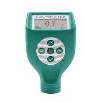
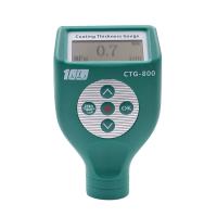
First, it should be known that any electronic coating Thickness Gauge will produce a value every time it is placed on a coated surface unless the battery is dead. The value may even be negative. The question is, does it represent the true thickness of the coating?
That depends. This is where the laws of physics come into play. Ever heard of Newton's third law? I bet you have. Newton's third law states: "For every action, there will be an equal and opposite reaction." Using a coating Thickness Gauge, we introduce an action (magnetic or electromagnetic field or eddy current) and explain the response with algorithmic equations. The results are presumed to be the thickness of the coating. However, as with any equation, appropriate variables need to be assigned, and we need to manage variables in order for the interpretation to be accurate.
What are these variables? They have been identified by the meter manufacturer and can be found in the manufacturer's specifications, which are usually listed in product literature, operator manuals, and websites. They include specifications such as minimum measurement area, minimum substrate thickness, temperature coefficient, measurement range, and of course a tolerance statement.
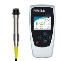
Selecting the right instrument is complicated because many gauge manufacturers offer a variety of sensors and special methods that directly address the complex application problems found in today's engineered products. Basically, you need to evaluate your application, identify your variables and look for a match, or (better yet) communicate those variables to your instrumentation supplier and let them make a recommendation.
One of the more common misconceptions I come across is what I call a "plug and play" mentality. Many of us get carried away by this kind of thinking these days. Our expectation is to take a product out of the box, plug it in and play it. This simply does not apply to coating thickness Testers. They need to be configured and don't solve the problem.
For example, while attending a finishing industry trade show, I had the opportunity to have valuable conversations with attendees about applications. A common mistake I find is that there seems to be a lack of understanding of the part geometry that the electronic gauge needs to set up. One attendee approached me and said, "I like your products, but they don't look good on round parts."
This strikes me as odd, since I've been in the game for almost 20 years, and it never occurred to me to have difficulties with surfaces. As it turned out, the guy was setting up his gage and verifying the accuracy of a flat sample and then taking measurements on round parts. Everything is explained there.
With most electronic gauges, you need to set up the instrument to the same surface properties and geometry as the part or assembly to be measured. this is very simple. You take an uncoated part, and read a "zero" value. This gives what we in the industry commonly refer to as a "zero reference" gauge. It records the physical properties of the component and takes into account three variables: the metallurgical composition of the substrate, the surface geometry and the surface-to-probe distance.
some geometric effects
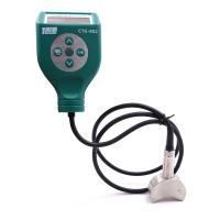
Speaking of distance, that’s what a coating Thickness Gauge measures. The instrument uses a probe or sensor to generate a signal that travels through the coating to the substrate. As Newton stated, once the signal reaches the substrate the reaction occurs. Distances need to be referenced from a starting point (i.e. the "zero reference" noted earlier). This starting point needs to remain constant in order for the output or coating thickness values to be accurate and reliable. For example, if you set the start point as a plane, and then change the rule by measuring the radius, the output (thickness reading) will be skewed. This is easily shown in the illustration on the previous page. As you can see, the instrument is first placed on a flat surface and then used to measure round parts. Flux lines increase travel, but the increase is due to part geometry, not coating thickness. The gauge will display a positive value and indicate the presence of a coating even when no actual coating is present.
The example is fairly obvious at this point, since we know that the surface of the part is not coated. However, depending on the extent of the radius or surface geometry, the error may not be obvious. What is happening in these cases is that the instrument readings are exaggerating the true amount of coating present. This could prompt finish line managers to dial down the amount of paint applied to meet specs. As a result, managers unknowingly applied less than the specified amount of paint, which obviously adversely affected the longevity, performance, and/or "first impression" of the product.
Also, the opposite is possible. If you unknowingly pick up and start using a gauge previously set up on a curved surface, and use it to measure a coating applied to a flat surface or an area with a small profile, the results may lead you to believe that you need to increase the The gauge underestimates the true coating thickness, so the coat volume is large.
Therefore, measurement accuracy is largely dependent on the part surface profile used for the initial gage setup and the surface profile of the part being measured.
more variables
Another variable that affects thickness measurement accuracy is called edge effects. This happens when the measurement is too close to the edge of the part. Electromagnetic flux lines leak over the edges, resulting in longer lines than would be confined to a plane.
This is where it is important to know and respect the minimum measurement area for a particular Detector to prevent that variable from deviating from that equation. Probes and sensors are designed to address this variable, and accurate measurements are simply a matter of addressing and meeting this requirement.
Another condition that exists is part surface profile, sometimes called surface roughness. This can come from surface preparation, for example in the form of surface blasting. It can also be a feature in manufacturing, such as many castings.
Regardless, the surface profile will affect the displayed coating thickness value. It will always cause the instrument to exaggerate the true thickness of the coating. The greater the roughness of the surface, the greater the reading deviation. I know of nothing in the gauge manufacturer's specifications or operating instructions to give you a specific value or "compensator" to remove the effect of surface roughness. The reason is because the surface roughness varies, the extent of which can only be determined by measurement.
The method needed to determine the effect of surface roughness is to take the same part and remove the roughness. Optimize the coating thickness Tester as normal, following the manufacturer's instructions.
Next, take a series of readings and calculate the average of these readings to determine the average and effect of surface roughness. How many readings are needed? The real answer is that you can stop reading when the reading you just finished no longer affects the average significantly. Many meters on the market today have built-in statistics and can automatically do the calculations for you.
The average of your readings is compared directly to the smooth surface of the same part or assembly with the values and effects of surface roughness. This value or factor then needs to be subtracted from all coating thickness measurements made on the coated surface of the same profile. If you don't, you'll exaggerate the true thickness of the coating.
Keep in mind that surface finish will often vary from part to part and from different areas of the part. Therefore, it is important to take a series of readings over an area and express the coating thickness value as a range that includes one or two standard deviations in the expression. This method results in greater certainty of the true thickness of the coating.
In general, microscopic surface roughness in combination with thicker coatings is easier to control than, for example, significant surface roughness in combination with thinner coatings. In fact, if you do the math, you can see that in some cases, if the coating being measured is very thin, surface roughness can completely eliminate any degree of certainty in the measurement.
Some gauges on the market have a built-in ability to subtract a constant from the calculated measurement. This is a handy feature for quick spot checks, but it's a single value, and as mentioned, surface roughness will vary. It is always good to express coating thickness values in terms of a mean spread of one or two standard deviations.
There are other factors that can affect the accuracy of coating thickness values. However, by following some simple rules, these factors can often be minimized - if not eliminated entirely. Always optimize the uncoated sample to be the same as the part or sample to be coated. During optimization, an attempt is made to replicate the environmental conditions that the gauge will encounter when measuring coated parts. While this may sound like a rather tedious and time-consuming exercise, there are many devices on the market that can store many gauge settings in memory and recall them when needed. Keep in mind that any compromises made during meter optimization are likely to affect the accuracy of coating readings and performance.
If you discover any of these limitations and find yourself at a point of compromise, you'll likely struggle to make your gauge fit your application. This can be expensive. Do a little research to find the right meter for your application. Remember, there is a price and then there is a cost. The last thing you want is to jeopardize a good first impression.