1. Constant temperature operating conditions
In the predetermined amount of coating, the liquid film forms a constant temperature operating condition at the coating nozzle to ensure coating uniformity. Regarding the constant temperature at the coating inlet, if the temperature of the coating liquid at the entrance of the coating nozzle is different from the temperature of the coating nozzle itself, the coating nozzle becomes a heat exchanger, and the result is that the coating liquid flows from the inlet of the distribution chamber to the end When the temperature of the solution changes, the change of temperature will cause the change of viscosity and the uneven thickness of the coating film.
For water-soluble solutions, such as gelatin solutions, the temperature and concentration dependence of viscosity has the following empirical formula model
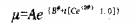
where µ is the dynamic viscosity, Pa·s
φ——solution volume fraction [1] 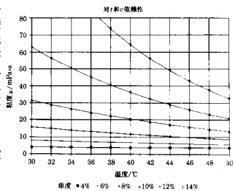
t —— solution temperature, c
A, B, C and D are material constants, which need to be determined experimentally for the specific material constants used. From the formula 2.21 calculate the viscosity ~ temperature coefficient. As an example, Figure 2.15 shows the dependence of µ on φ and t for water-gelatin. The specification of gelatin is unknown. Apparently, the viscosity of 10% gelatin solution 60 will change by 4.5% for every change of ℃ at 40°C. Large variation in thickness. This simple estimate demonstrates the importance of constant temperature operation.
2.8.2 Temperature change of the coating liquid flowing along the distribution chamber
The temperature distribution of the coating solution is calculated as a function of the coordinates along the x-axis of the distribution chamber (see figure) using standard integral analysis. The following assumptions can be made:
.Constant material temperature of applicator nozzle
.The flow of liquid in the distribution chamber is similar to the flow in a circular pipe
.The laminar heat transfer coefficient in a circular pipe is according to formula 2.22
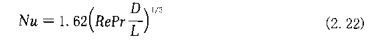
Nu in the formula - Nusselt number
Re — Reynolds number of pipeline flow
Pr —— Prand number
D - pipe diameter, m
L —— pipe length, m
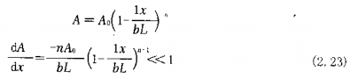
.The cavity section changes according to the following formula
.As the liquid flows into the dosing (squeeze) slit, the flow rate decreases linearly according to
In the formula, qt——volume flow rate, and /s
qt0——volume flow rate at the inlet of the cavity, m3/s
The solution of the thermal differential equation becomes
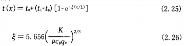
In the formula §——Thermal resistance
t ——coating liquid temperature, ℃
t0 ——The temperature of the coating solution at the inlet of the cavity, ℃
t1 ——coating nozzle tank temperature, ℃
K —— fluid thermal conductivity, W/(m K)
P——fluid density, kg/m3
c1——specific heat capacity at constant pressure, J/(kg• K )
qv——Volume flow per unit width of coating nozzle, m2/s
The formula (2.26) shows that the temperature of the coating liquid and the coating tank gradually tends to be consistent under the opposite action of the driving force and thermal resistance at temperature Δt=(t1-t.). Whether it is the coating width or the viscosity of the coating liquid affects the temperature distribution "the change of the temperature of the inlet and outlet of the coating liquid cavity is exacerbated by the following factors.
.Excessive temperature difference between the coating fluid at the chamber inlet and the nozzle body (a measure of isothermal operating conditions).
.High thermal conductivity and low heat capacity Dong .
.Small volume flow per unit coating width (equivalent to low coating speed and thin layer coating in predetermined amount coating .
This situation is often encountered in pilot plant coating in product development, which indicates that the pilot plant needs good temperature control.
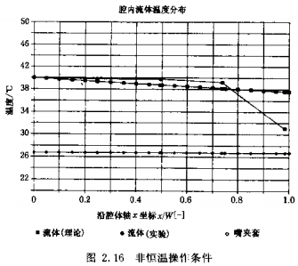
The example given in Figure 2.16 is a comparison of theoretical and experimental temperature distributions. Temperature t, = 26. 7'C (constant) • t0= 40.0 ℃, △t=13. 3 ℃ , ζ=0.2. As can be seen, the theoretical and experimental data are in good agreement through more than 75% of the cavity length, but the actual temperature change near the end of the cavity is larger than the theoretical prediction.
如果用同样的一维数学预示涂布嘴驻留时间特性时,可以观察到类似的理论和实际的矛盾。
According to在腔体三维抛物线流体流动的可视化实验观察.已经显示出这一矛盾的原因。流体在管线中流动到达涂布嘴直到
体流向腔体的端部和进入到定量(挤压)间隙靠近壁处的流速都很小。整个过程这些流体单元的低流速说明了驻留时间长的原因,相当T长时间曝踩丁热传递,造成对温度分布的影响。
实验数据指出,According to具体的操作条件,流体在腔体进口和木端最大温度差的实验值预计比理论值低1/2~1/5。
3、温度控制要求
无恒温操作条件对涂布厚度在涂布宽度的一般(中间进料)或整个宽度上的影响可以用方程(2. 4)中给出的项积分来估计。
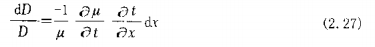
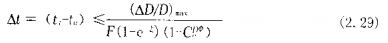
偏导数可以从式 (2. 21) 和 (2. 25) 求得, 结果如下:
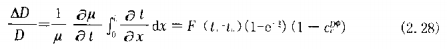
式 (2. 28)右侧部分可以再安井成仵腔体进口处涂布液和涂布梢体间的最人温度并的 要求, 因此由无恒温操作条件所造成的涂伈肝反不均匀度个超过预测数值9
对千照相工业典型涂布条件最大温度差的数壮级为0. 5"C, 这一点没有相当的研究是不容易认识到的。
4、温度控制系统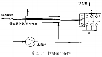
一个完整的温度控制系统应包括加热和冷却。对只有凝冻性的涂布液如明胶,具温度稍点高于凝固点, 不需冷却以防止在输送系统和涂布嘴内造成涂液凝冻。 对此种场合, 推行涂布液输送温度刚好低于涂布温度,然后在控制热量的流体作用下逐渐接近涂布温度。提供的热交换系统本身包括如下装置。
.微波能:对于有效在线热交换器,这种系统热能输入可以容易地山在涂布嘴的调温水的温度设定点来控制。
.静态混合器/热交换器静态混合器也可以用作为有效套管热交换器。 凭借特殊的混合兀件的设计, 其总传热效率比无混合元件的空管高出一个数量级,准确的传热系数由静态泥合器制造厂提供。
如果流经外壳的热水和涂布嘴调温水由同一回路供应,则两个系统有同样的温度设定点。如果热交换器有足够大的尺寸,涂布液的温度和涂布嘴的温度会渐渐的趋向一致。
This heat exchange system is characterized by its simplicity, without moving parts and control loops, however, according to the specific application requirements for constant temperature operating conditions, due to the temperature inside and outside the tube slowly tending to the same, the length of this simple sleeve heat exchanger may become too long (tens of meters). In this case, it is recommended to supplement the thermal energy with hot water of appropriate temperature or microwave energy, and this countermeasure will lead to a reduction in the cost of complicated peripheral equipment (including feedback loops) of the heat exchanger, etc.