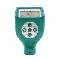
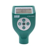
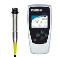
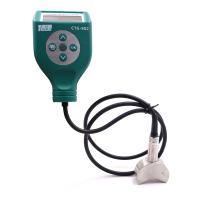
The PosiTector 6000 probe measures the thickness of metallic coatings non-destructively. Three steps ensure great accuracy...
Calibration - Usually done by the manufacturer. All probes include a calibration certificate
Verification - Usually done by the user against known reference standards such as plastic shims or coating thickness standards.
Adjustment - known thickness
calibration
Calibration is the advanced, controlled and documented process of measuring a traceable calibration standard over the entire operating range of the probe and verifying that the results are within the probe's stated accuracy. Calibration is performed by the manufacturer, its authorized agent, or an accredited calibration laboratory using documented procedures in a controlled environment.
PosiTector 6000 probes are supplied with a certificate of calibration showing traceability to national metrology institutes. For organizations with recertification requirements, probes may be returned periodically for calibration. DeFelsko recommends customers establish calibration intervals based on their own experience and work environment. Based on DeFelsko's product knowledge, data, and customer feedback, a one-year calibration interval from the last date of calibration, date of purchase, or date of receipt is a typical starting point. Written calibration procedures are freely available online.
verify
Validation is an accuracy check performed by the user against a known reference standard. Successful verification requires the Gage to read within the combined accuracy of the probe and reference standard.
A reference standard is a sample of known thickness against which the user can verify probe accuracy. A reference standard can be a plastic shim, a coating thickness standard, or a sample part whose coating thickness has been determined using other methods.
Verify accuracy at the start and end of each work shift. During a work shift, if the Gage is dropped or suspected to be giving false readings, it should be re-verified for accuracy. In case of physical damage, wear, high use, or after established calibration intervals, the probe should be returned to the manufacturer for repair or calibration.
Adjustment
Tuning or Calibration Tuning is the physical behavior of aligning probe thickness readings to match samples of known thickness (removing bias) in order to improve the range of probe accuracy on a specific surface or specific part of it being measured. 1-point or 2-point Cal adjustments are possible.
The probes are factory calibrated and perform an automatic self-test each time a measurement is taken. For many applications, no further adjustments are required after reset . Simply check ZERO on an uncoated substrate, then take your measurement. However, sometimes probe readings are affected by variations in substrate shape, composition and surface roughness, or by measuring different locations on the part. This is what makes Cal adjustments possible.
![]() The symbol disappears whenever a calibration adjustment is made .
The symbol disappears whenever a calibration adjustment is made .
If the calibration adjustment method has not been specified, use the 1-point method first. If measuring a shim on an uncoated surface shows inaccuracy, use the 2-point method. The factory calibration settings can be restored at any time by performing a reset , creating new calibration settings (see Calibration Memory ), or deleting adjustments made to the Calibration 1 calibration settings.
![]() The symbol will appear on the display whenever the factory calibration settings are used .
The symbol will appear on the display whenever the factory calibration settings are used .
For "FN" probes, calibration adjustments are only made for the "F" or "N" mode (stored independently under a specific calibration), regardless of which was last measured.
Calibration menu
1 point calibration adjustment
Also known as offset or correction value, there are 4 ways to perform this adjustment:
(i) Simple zero calibration adjustment
Measure uncoated parts. If the Gage does not read "0" within the tolerance range of the probe being used, lift the probe from the surface and adjust the display down (-) or up (+) until it reads "0". Measure and adjust until the average of a series of readings on the uncoated surface is within the tolerance of "0".

(ii) Mean Zero Calibration Adjustment
To establish a "0" on a rough or curved surface, the preferred method for (i) is to take several readings on the uncoated section and average the results.
(a) Select Zero from the Cal Settings menu.
(b) Press (+) to select the reading used to obtain the average reading, usually 3 to 10 readings. The greater the difference between the readings, the more readings are averaged.
(c) Repeated measurement of the uncoated section. After placing the probe on the surface, the Gage will wait 2 seconds for the user to properly position the probe on the surface. After the last measurement, the Gage will calculate a zero, which represents the average of all zero readings.
(iii) Simple adjustment to known thickness
Sometimes it is desirable to adjust the gage to a known thickness, such as a shim, rather than adjusting it to zero.
Measure objects. If the expected reading is not obtained (within tolerance), lift the probe from the surface and adjust the displayed reading down (-) or up (+) to the expected thickness. Press and hold the button to increase the adjustment rate.

(iv) Average adjustment to known thickness
On rough or curved surfaces, the preferred method of (iii) is to take several readings of the known thickness and average the results.
(a) Select 1 Pt Adjust from the Cal Settings menu.
(b) Press (+) to select the reading used to obtain the average reading, usually 3 to 10 readings. The greater the difference between the readings, the more readings are averaged.
(c) Repeated measurements of a known thickness reference. The Gage will wait 2 seconds between readings to allow the user to properly position the probe on the surface. After the last measurement, the Gage will calculate and display a reading that represents the average of all measurements. If the expected reading is not obtained (within tolerance), probe the probe from the surface and adjust the reading down (-) or up (+) to the expected thickness and press![]() .
.

2-point calibration adjustment
Preferred method for very unusual substrate materials, shapes or conditions. Provides greater accuracy within a limited range of definitions.
1. Select 2 Pt Adjust from the Cal Settings menu.
2. Press (+) to select the number of readings used to average thinner items, usually 3 to 10 readings. The greater the difference between the readings, the more readings are averaged.
3. Repeatedly measure thinner items. The Gage will wait 2 seconds on the surface to allow the user to properly position the probe on the surface. After the last measurement, the Gage will calculate and display a thickness value representing the average of all readings taken using the factory calibration settings.
4. Lift the probe off the surface and adjust the displayed reading down (-) or up (+) to the known thickness value of the thin item. Press to accept the value.
5. Repeat steps 2 - 4 for thicker projects.
![]() Cal Lock
Cal Lock
After selection,![]()
The icon will appear and all calibration settings are "locked" to prevent further user adjustments. Uncheck for further adjustments.
![]() N lock
N lock
(FN ferrous/non-ferrous combination probes only)
When working regularly on non-ferrous metal substrates, choose N-lock (non-ferrous metal lock). The ![]() icon will appear and the probe will only use the eddy current principle reducing measurement time and extending battery life.
icon will appear and the probe will only use the eddy current principle reducing measurement time and extending battery life.
N Lock is very useful when measuring coated steel plates. Typically, probes use the magnetic principle to measure coatings + platings on steel. N Lock causes the Gage to measure only the coating on the plated layer.
Select N Lock to measure slightly magnetic substrates; i.e. gold clear coats on nickel-plated brass. While the probe's magnet is used for the magnetic principle, it is also used for N-type locking to magnetically saturate the lightly magnetic substrate and allow the eddy current principle to operate unimpeded.
NOTE: When using the N lock, readings can be obtained when measuring non-conductive coatings on steel. This is not recommended.
Calibration memory
 (advanced models only)
It's often convenient to store a specific calibration adjustment before making another one. Then, if you return to that section, you can restore the corresponding calibration settings. A "setting" is any calibration adjustment. The PosiTector 6000 always shows the current calibration setting (example: Cal 3 in the upper right corner of the display). The setting called Cal 1 has a unique function. It can be tweaked but never deleted, and is always activated with factory settings after a reset .

Create a new calibration setup using the next available number (up to 10). By default, these new calibration settings were initially created using Gage's factory settings. use![]() Icons appear at the bottom of the display. If a batch is open and has readings, a warning message will prevent a new calibration memory from being created. First delete the batch.
Icons appear at the bottom of the display. If a batch is open and has readings, a warning message will prevent a new calibration memory from being created. First delete the batch.

Load existing settings. Scroll using the Up or Down button until the desired setting appears and press ![]() . If a batch is open and has readings, a warning message will prevent the stored calibration setup from being opened. Start by creating a new batch or opening a batch that does not contain reads.
. If a batch is open and has readings, a warning message will prevent the stored calibration setup from being opened. Start by creating a new batch or opening a batch that does not contain reads.

Removes the setting completely from the list. This Cal number can be reused later using the New command. If readings are stored into a batch using that calibration setting, the setting cannot be deleted. All reads in the batch are first deleted. While Calibration 1 cannot be deleted, the delete function will restore it to factory settings.

View stored calibration settings.