Use of MODEL3331


1. [ MODE ] key:
1a. In the measurement mode, press this key to cycle through the display of conductivity value and temperature value or resistivity value and temperature value.
1b. In the setting mode, press and hold this button for three seconds, and the whole machine will return to the previous setting parameter. 2. [ UP ] key:
2a. In calibration mode, press this key to display the previous calibration item. In setting mode, press this key to display the previous
a setting item or increase the value of a setting item.
2b. In the measurement mode, press this key and [ENTER] key at the same time, the machine will enter the calibration mode.
3. [ DOWN ] key:
3a. In calibration mode, press this key to display the next calibration item. In the setting mode, press this key to display the setting item or decrease the value of the setting item.
3b. In the measurement mode, press this key and [ENTER] key at the same time, the machine will enter the setting mode.
4. [ ENTER ] key:
In the calibration and setting mode, press this key to store the set parameters into the EEPROM memory, and enter the next page or next page of parameter setting.

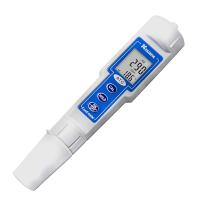
1. Main Display – Used to display conductivity/resistivity and temperature values.
2. CAL – indicates that the whole machine enters the setting and calibration mode.
3. mA - When mA is displayed, it means that the whole machine is in the setting mode of 4mA or 20mA.
4. MΩ – Unit of resistivity.
5. ℃ – Temperature unit.
6. uS – Unit of conductivity.
7. ATC – When there is this display on the LCD, it means that the temperature at this time is automatic temperature compensation, and the machine uses a temperature probe to sample temperature signal.
8. MAN – When this display is on the LCD, it means that the temperature at this time is manual temperature compensation, and the machine has a fixed as the sampling value of the temperature.
9. mS – Conductivity unit.

1. The range of AC power used by Model 3331 is 100~240V; 50/60HZ. When installing the machine, it is necessary to correctly connect the AC power to the terminal, and make sure that the "E" of the machine is fully connected to the ground of the AC power.
2. 正确连接电流输出到4-20mA的接线端子上,注意正负极。电流的输出负载最大不能超出500欧姆。
E. 测量模式
接通电源开机后,整机会进入测量模式。 使用者可按[MODE]键去选择电导率、温度显示或者电阻率、温度显示两种模式。

1. 电导率 – 电导率测量模式,时时显示电导率的测试值。
2. 电阻率 – 电阻率测量模式,时时显示电阻率的测试值。
3. 温度 – 温度测量模式,时时显示温度的测试值。
【注意】: 在测量模式按[MODE]键,显示将在电导率及温度或者电阻率及温度两种模式上切换。
F. 设定模式
同时按住[DOWN]键和[ENTER]键,整机将进入设定模式。
1.温度补偿模式的选择

在此界面,按[UP]键或[DOWN]键可循环切换两种温度补偿模式:01(热敏电阻:10k欧姆)、02(手动)。
选择正确的温度补偿模式后,按[ENTER]键存储,并进入下一个设定项目。
2. 温度系数的选择:

在此界面,按[UP]键或[DOWN]键可循环切换温度系数值:E2.00, E0.00。 选择正确的温度系数值后,按[ENTER]键存储,并进入下一个设定项目。
3. 电导电极常数的选择:

在此界面,按[UP]键或[DOWN]键可循环切换电导电极常数值:C1.00, C0.10 和 C0.01。(C1.00:K=1.00;C0.10:K=0.10;C0.01:K=0.01)
选择正确的电导电极常数值后,按[ENTER]键存储,并进入下一个设定项目。
4. 测量范围的选择:
在此界面,按[UP]键或[DOWN]键可循环切换不同电导电极测量范围值:CF01/0.000~1.999uS/cm, CF02/2.00~19.99uS/cm, CF03/0.05~0.50MΩ, CF03/0.50~19.99MΩ(电极常数 K=0.01) 或者 CF01/0.00~19.99uS/cm, CF02/20.0~199.9uS/cm(电极常数 K=0.10)或者 CF01/0.0~199.9uS/cm, CF02/200~1999uS/cm, CF03/2.00~19.99mS/cm (电极常数 K=1.00)。选择正确的测量范围后,按[ENTER]键存储,并进入下一个设定项目。


5. 4 mA 输出设定:

在此界面,按[UP]键或[DOWN]键可调整 4mA 输出对应的电导率值或电阻率值。
调整到所需的电导率值或电阻率值后,按[ENTER]键存储,并进入下一个设定.
6. 20mA 输出设定:

在此界面,按[UP]键或[DOWN]键可调整 20mA 输出对应的电导率值或电阻率值。
调整到所需的电导率值或电阻率值后,按[ENTER]键存储,整机结束所有设定项目,回到测量模式
G. 电导率/电阻率校正模式
Model 3321采用单点校正。
在测量模式,同时按住[UP]键和[ENTER]键,整机将进入电导率/电阻率校正模式,“CAL”字体将显示并且显示一个电导率/电阻率的当前测量值。
用去离子水清洗电导率电极并把电极放入适当的标准溶液中,待温度稳定后,按[UP]键或者[DOWN]键调整此当前测量值到标准溶液值,然后按[ENTER]键存储。此时完成标准液的电导电极校正。
H. 4-20 mA 输出
1. Isolation voltage:
The isolation voltage of the isolated current output between the complete machine and the load is 500 VDC, if it exceeds this isolation voltage, it may cause damage to the complete machine.
2. Isolated current load:
The maximum load of the isolation current is 500 ohms, if the load exceeds 500 ohms, it may cause an error in the isolation current output.
3. Conductivity isolated current linear output
The output of the conductivity isolation current is a linear proportional output according to the setting of the user on the isolation current setting interface.
The output formula of current: mA(output) = 4mA+(16mA)*(D – U4mA ) / (U20mA- U4mA)
Where: mA(Output) = Output value of the isolation current
D = current display value of conductivity or resistivity
U4mA = Conductivity or resistivity setpoint at 4 mA
U20mA = Conductivity or resistivity setpoint at 20 mA