Overview: In this paper, the determination of the adhesion strength of the emerging coating (single pendulum impact scratch method) is mainly analyzed from two parts: the structure and measurement principle of the single pendulum impact scratch instrument and the binding strength of the electroless Ni-P layer. This new single pendulum impact scratch method can effectively evaluate and quantitatively detect the bonding strength of the fixed plating (coating) layer and the substrate and the wear resistance of the plating (coating) layer under impact load. According to the test of the bonding strength of Ni-P electroless coating and carbon steel by impact scratch method, the bonding strength and bearing capacity of Ni-P electroless coating and substrate can be enhanced by maintaining a certain surface roughness of the substrate, controlling the carbon content of the substrate and selecting a reasonable heat treatment temperature.
The coating material is mainly due to good physical and chemical properties to protect and decorate the substrate or give the substrate a certain function. So far, the coating materials, processes and properties have been recognized in the fields of corrosion prevention, wear resistance and decoration, and the combination of the plating (coating) layer and the substrate is a very important performance for any application. There are a variety of methods to evaluate the bonding strength, such as scratch, tensile method, bending method, torsion method, and erosion method, but they all boil down to the layer-substrate interface in some way by applying a force that can be accurately measured to destroy the layer-substrate interface, and use it to characterize the bonding strength.
In fact, most coatings are so thin that it is difficult to apply an external force that has a precise meaning and is easy to measure. Therefore, exploring a new simple and effective method to evaluate the bonding strength has always been an important topic in the field of surface engineering. Electroless Plating Ni-P has attracted much attention for its superior uniform plating ability, mature process and reasonable performance-to-price ratio. By adjusting the phosphorus content and heat treatment conditions, the coating can be corrosion-resistant, wear-resistant, or both. Ni-P plated devices on carbon steel substrates can replace stainless steel products or hard chrome plated parts under some conditions, but its excellent performance first requires it to have a strong bond with the substrate. In this paper, a new method for quantitatively evaluating bond strength, the single pendulum impact scratch method, is introduced. The bonding strength of Ni-P electroless coating with steel and the wear resistance of the coating under impact load were quantitatively evaluated by a simple test instrument, and several factors affecting the bonding strength of the coating were discussed.
1 Introduction to the single pendulum impact scratch method
1. 1 Principle of instrument structure
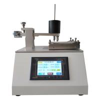
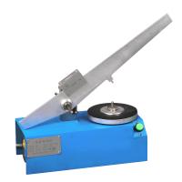
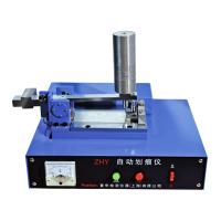
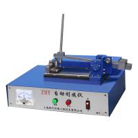
The single pendulum impact Tester has long been known and used to determine the impact toughness of materials. If a rigid scratch is set at the bottom of the pendulum to make it impact across the surface of a plate-shaped sample instead of breaking the strip specimen, a groove can be carved from shallow to deep, from narrow to wide, and then exiting the surface after passing through the deepest (wide) point. The test equipment is modified with an impact testing machine, i.e. a conical or diamond-conical carbide slash is fixed at the bottom of the pendulum. A single pendulum impact scratch meter is formed by placing a platform that can be used for precision lifting at the original sample stage, and installing a sensor under the stage that can sense the normal and tangential forces of impact scratches, together with the original disc swing angle Tester [1]. The working principle and device configuration block diagram are shown in Figure 1.
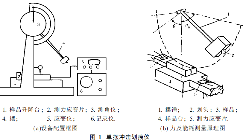
According to the functional principle, the scratch energy consumption E can be calculated from the difference in the swing angle of the impact scratch
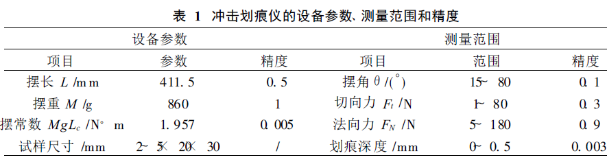
E = MgLc ( cosθ- cosθ0 ) ( 1) where MgLc is the pendulum constant; θ0 and θ are the initial swing angle and the post-scratch swing angle. The equipment parameters, measurement range and accuracy of the single pendulum impact scratch meter used in the test are listed in Table 1.
1. 2 The principle of impact scratch method combined with strength determination
When the pendulum rushes towards the specimen at a certain initial velocity, the tip of the tip of the hammer first touches the surface of the specimen, then pierces and cuts the surface layer, and then skims out the specimen. The entire scratch undergoes a process of elastic contact, plastic deformation, fracture, etc., which lasts only a few milliseconds. If the specimen is coated and the maximum depth of scratch invasion is greater than the thickness of the coating, and the impact energy of the swing head is sufficient, the scratching process must include the scratch loading cutting into the coating, passing through the layer/base interface, entering the substrate, and then unloading and exiting the substrate, passing through the interface and plating to skim out of the surface of the specimen. As long as a series of impact scratch tests are done from shallow to deep, when the invasion depth reaches and exceeds the thickness of the coating, that is, the scratch head crosses the layer base interface, there will be discontinuous abrupt points on the curve of the tangential force of the scratch, the impact energy consumption and the depth of the groove with the length of the scratch. The one-dimensional scratch model can be used to calculate the energy dissipated by the failure of the layer/substrate interface per unit length, which can be used as a representation of the bonding strength of the coating to the substrate. From the scratch model in Figure 2, the binding strength is calculated as follows [2].
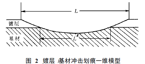
E real = Ecl - Ecl′+ Esl′+ Δ ( 2) where E is the energy consumption of the crossed head invading layer/base interface measured experimentally, and the trace length is L; ECL is the energy consumption when the scratch occurs only in the plating and the length is L; Ecl′ is equivalent to the energy consumed by the plating when the substrate is exposed to length L′; Ecl and Ecl′ are derived from the fitting equations of energy consumption (E) and mark length (L) in a series of coating scratch tests. Esl′ is the energy consumption value when the scratch length of the substrate is L′, which can be obtained from the relationship between the energy consumption (Es) of the impact scratch of the substrate and the length of the groove (L). Δ is the difference in energy consumption. The amount of the characterization of the binding strength is X( J/mm) , which can be calculated from the following formula
It should be noted that this is a simplified model of a three-dimensional scratch that treats a three-dimensional scratch in one dimension, and it is suitable for scratch heads that are almost non-wearable, i.e. the maximum width of the groove does not change for the same scratch length. The data obtained not only have a clear physical meaning, but also have relative comparative value.
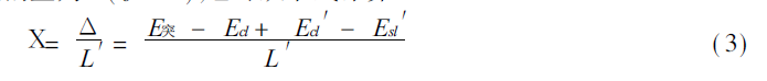
Fig. 3 shows the variation curves of the normal force (FN) and tangential force (Ft) of the electroless plated Ni-P layer on the 45# steel sheet with the scratch length in the impact scratch. The abrupt point that occurs as the scratch head passes through the layer/base interface can be seen from the Ft. Select the normal force (FN) corresponding to this point and define it as the critical normal force (FNC) for breaking, which can be used as the bearing capacity of the coating or can be used to infer the layer/base bond, which is equivalent to the critical load (Lc) in the general (quasi-static) scratch method. In addition to reflecting the bonding, its value will also be affected by factors such as coating thickness and hardness. In contrast, neither FNC nor Lc (Scratch Critical Load Value) is less clear than X(Δ /l′).
2 Electroless plating The bonding strength of the Ni-P layer
2.1 Preparation of specimens
The formulation of medium phosphorus electroless plating solution is shown in Table 2.
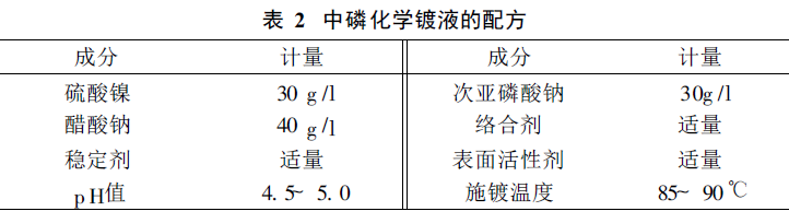
First, the surface of the 40 mm× 28 mm× 3 mm 45# steel plate to be plated is cleaned, and then quickly transferred to the electroless nickel plating solution after activation. During plating, the p H value of the plating solution was adjusted with 1∶1 ammonia water, and a Ni-P coating with a thickness of 15~20μm and a phosphorus content of 7%~12% could be obtained after about 1 h.
2. 2 Single pendulum impact scratch test procedure
Place the coated specimen horizontally on the sample stage, adjust the position so that the tip of the pendulum stroke touches the surface of the sample, and use the dial gauge reading as the base point of the table liter. The initial swing angle (60°) is selected, the pendulum is released freely to make it across the surface of the coating, and the tangential and normal force signals are recorded with a dual-trace memory oscilloscope, and an energy consumption can be calculated after a scratch. There are about 10 scratches from the coating layer to the interface of the elevated sample stage at the same height, from which the relationship between E and L and the exposed length of the substrate L′ can be measured. These data are used to fit the equation between the energy consumption of the plating layer and the length of the groove, and then the equation is fitted from a series of scratches on the substrate and the corresponding energy consumption relationship, and they are listed in a table for later use. Select the scratches that penetrate the coating and the substrate and are exposed to the interface of sufficient length, deduct the Ecl and Esl′ from the E solid, add Ecl′, and divide by the exposed length of the substrate L′ (see equation (3)) to obtain the bonding strength X.
2. 3 The effect of the surface roughness of the substrate on the bonding strength

2. 4 Effect of carbon content of steel on the bonding strength of Ni-P layer
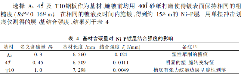
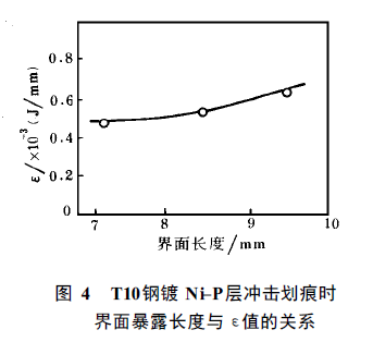
Due to the different carbon content of steel, the failure of the coating and the substrate during impact scratches also has its own characteristics. Table 4 shows the phenomena seen when looking at scratches with SEM. The bonding strength of the layer/base decreases with the increase of the carbon content of the substrate, and the hardness of the steel with different carbon content will affect the measurement of the energy consumption value, so the desired Esl′ value should be calculated using the respective relationship between Es and L when calculating X. The Ni-P coating of the T 10 steel substrate was calculated by three scratches at different depths of intrusion, and the change in bond strength (X) as a function of the interfacial exposure length (L′) is shown in Figure 4. Although X shows an increasing trend with the increase of L′, its value remains in a narrow range. Therefore, keeping the interface exposure length similar, the X value of different substrates and coatings can still reflect the layer/substrate bonding strength. In general, the critical load value (Lc) measured by the scratch method increases with the change of layer thickness, and it is difficult to correct the measurement results. The X value measured by the impact scratch method hardly changes with thickness, which is also one of the characteristics of this method.
2. 5 Effect of heat treatment temperature on the bearing capacity of Ni-P layer
As we all know, the hardness of Ni-P plating can be adjusted by heat treatment. The 10μm thick 45# steel sheet was heat treated at 200°C, 380°C and 700°C for 1h, and the critical normal load (FNC) at the time of layer breakage was determined on a single pendulum impact scratch meter. Table 5 lists the microhardness (load 0.25N) and FNC of the coating.
Table 5 Effect of heat treatment temperature on Ni-P layer FNC
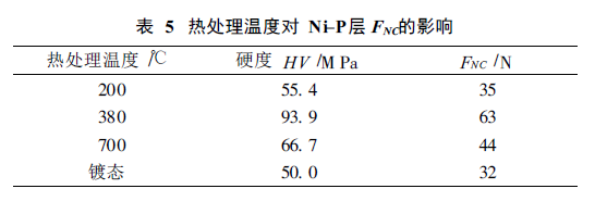
After heat treatment, the microstructure of Ni-P coating will change significantly, and 380°C treatment will promote the precipitation of Ni3P phase, resulting in a significant increase in the hardness of the coating. After treatment at 700°C, the strengthening effect of Ni3P particles was weakened due to the growth of Ni3 P, and the hardness decreased accordingly. The change of coating properties will affect the impact energy consumption during scratches, so the Ni-P layers after different heat treatments cannot maintain similar impact scratch failure characteristics. Therefore, it is difficult to calculate the layer/base bonding strength of heat treatment by measuring the E-L relationship from the scratches on the plated Ni-P layer and the rolled steel plate substrate, so only the critical normal force is used to express the bearing capacity of the system, and FN C can obviously also represent the bonding between the coating and the substrate to a certain extent. Compared with the plating state, the appropriate heat treatment temperature will improve the bonding of the layer/substrate interface, and the wear resistance of the plating under impact load will be improved.
3 Conclusion
The above experimental results show that the single pendulum impact scratch method can be used to determine the bonding strength of electroless Ni-P layer and substrate, and the energy consumed by the interface exposure per unit length can be applied to the quantitative characterization of the bonding strength.
Maintaining a reasonable surface roughness of the substrate (Ra≈ 0.16), controlling the carbon content of the substrate and adopting a reasonable heat treatment temperature can improve the bonding strength and bearing capacity of the coating and the substrate.
This article is mainly excerpted from Liu Weiwei and Chen Yuanru's "Determination of the Bonding Strength of Ni-P Chemical Coating by Impact Scratch Method"