There are many factors to consider when designing meaningful viscosity tests for adhesives and sealants.
Most people in the adhesives and sealants industry are aware of viscosity and realize that it is a characteristic of the way materials flow. Technically, viscosity refers to a material's resistance to flow; it can be measured in various ways, depending on the nature of the application. Evaluating how a material will be processed during manufacturing or how it will be applied by an end user is fundamental to determining the type of viscosity testing that should be performed.
Measuring caulk viscosity
Imagine a caulk gun. The squeeze force required to get the material out of the nozzle is important. If the caulk is not viscous enough, it will produce too much adhesive and some will be wasted. Also, caulk that does show up may not hold its place on the substrate. If the caulk is too viscous, it may not show up at all. In either case, the material was rejected and the customer was unhappy.
Quality control (QC) during manufacturing requires testing methods to predict problems before they occur. A way to simulate the squeezing action of a gun on a caulk is through a squeeze test. An instrument called a texture analyzer - with an extrusion unit - is ideal for this type of testing. This type of instrument, sometimes called a multimeter, basically applies compression or tension to a material. In this case, the instrument simulates the process of pushing material through a tube and out of a nozzle.
During this type of testing, the extrusion unit is filled with sample material. The small circular opening on the bottom of the battery represents the nozzle diameter through which the caulk will exit. Bring the disc plunger down into contact with the material on top of the cell. The test method is to move the plunger down into the battery at a defined speed. Material is discharged from an opening in the bottom of the cell. A load cell in the instrument monitors the resistance experienced by the plunger as it pushes down into the material. The key data recorded is force as a function of time and distance, which provides a complete characterization of the squeezing action required to force the caulk out of the gun.
Technically, this type of instrument is not a viscometer, but it can still measure the viscosity of caulk. The output parameter is the force required to extrude the caulk. This correlates with the amount of work the user has to do to get the caulk out of the gun. The importance of choosing a test method that correctly characterizes what is happening to the material cannot be overemphasized. Since many adhesive and sealant materials are applied from some type of gun, a texture analyzer becomes a relevant tool for testing.
shear rate
A key concept that is often not understood is that the viscosity of a material is not a single point measurement; it often depends on many factors. Take the caulk example above as an example. The speed at which the plunger pushes through the material will directly affect the measured force resistance. The faster the plunger moves into the caulk, the greater the force measured. Therefore, the rate of shear action on the caulk is greater and may result in different viscosity values.
A major challenge in understanding viscosity is realizing that shear rate plays a key role in determining resistance to flow. As mentioned earlier, it is necessary to consider how the material will be handled or disposed of when it is used. In order to have a relevant test method for measuring viscosity, the shear action should be analyzed.
For liquid glue, a Rotational Viscometer run at different speeds was used to simulate what happens to the material when stored in a bottle or applied to a substrate. The shear action of the glue shaking in the bottle is relatively low, whereas the application process of placing the glue can be quite high. Once the glue is applied, the shear action is again very low because only gravity is causing it to spread farther. An evaluation of how the glue will be used leads to the selection of an appropriate viscometer.
dynamic viscosity
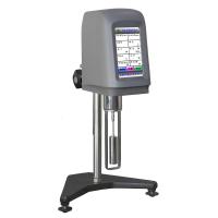
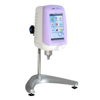
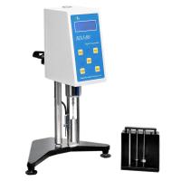
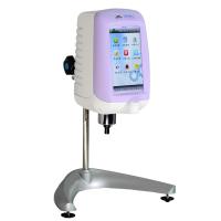
A Rotational Viscometer may be a common viscosity measurement tool. When inserted into the test material, the spindle rotates at various discrete speeds to shear the material at the exact shear rate. Viscometers measure the amount of torque resistance a material exerts on a rotating shaft at each speed. Torque measurements are quantified as shear stress acting on the portion of the spindle surface immersed in the material. Combining the measured parameter (torque) and the controlled parameter (spindle speed) into one equation, dynamic viscosity is defined as the ratio of shear stress to shear rate:
Dynamic viscosity = shear stress / shear rate
Centipoise (cP) is the unit of measurement commonly used to quantify rotational viscosity in North and South America; millipascal seconds (mPa.s) are commonly used outside the Americas (1 cP = 1 mPa.s). This one-to-one equivalence minimizes potential problems when comparing data between multinational manufacturing plants.
Distilled water is the baseline reference against which all other material viscosities are compared. The US National Institute of Standards and Technology (NIST) stipulates that the viscosity of water is 1 cP when measured with a capillary viscometer at 20 °C.
The choice of spindle for shearing a material depends on its general flow characteristics and historical priorities for viscosity testing. The standard disc spindle is commonly used because it has been around for over 75 years. Various other spindle geometries can also be used, depending on the amount of sample available and the viscosity of the material (see Figure 1). Available geometries include cylinders, cones, T-bars and vanes. Coaxial cylinders (cylindrical major axes in cylindrical chambers) and cones/plates are chosen when the shear action requires a defined shear rate.
Determining the shear rate
The choice of shear rate is determined by analyzing how the material is processed. Imagine this material sandwiched between two plates that are a fixed distance apart. If the bottom plate is held stationary and the top plate is moving at a defined velocity, the shear rate is the ratio of the velocity of the moving plate (V) to the distance (X) of the dividing plate
Ratio: Shear Rate = V/X
Countdown seconds (s-1) are the unit of measurement for shear rate. This method of quantifying shear rate assumes that the fluid behaves in a uniform (laminar) manner, as indicated by the arrows in Figure 2. The layers of molecules in the material stay in the same plane and slide against each other in such a way that the closer they are to the moving plate, the faster each layer moves.
The relevant shear rate for the application can be easily calculated by applying the above equation. When a spatula is used to place the adhesive on the substrate, the substrate and the spatula represent two plates. In order to lay down a 1 mm thick adhesive bead in an automated operation where the substrate moved at 50 cm/sec, the shear rate was 500 sec −1 . This becomes one of the shear rates that should be used in QC testing.
flow behavior
Considering the above concepts about relative shear rates, it can be seen more clearly that viscosity may not be a single number for a given material. The idea is to test the material with the viscometer at different rotational speeds (i.e. different shear rates) and observe the measured viscosity values.
A common flow behavior is called pseudoplasticity (or shear thinning), where the viscosity of a material decreases as the shear rate increases. Figure 3 is a rheogram illustrating the behavior of liquid adhesives tested at relatively low shear rates. Most adhesive and sealant materials exhibit pseudoplastic behavior; for example, body fillers are highly viscous materials with pronounced pseudoplastic flow. Figure 4 shows that the apparent viscosity drops sharply when the shear rate increases to 100 s-1, and then gradually decreases above the shear rate.
A related issue that affects measured viscosity values is the length of time that shear is applied to the material. When a material is sheared at a constant rate and the measured viscosity decreases with time, the flow behavior is called thixotropy. Many adhesive and sealant materials exhibit thixotropy; it is important to consider whether the viscosity returns to its original value once the shear action ceases, and whether this behavior is desired or expected. Once the bead is placed on the substrate, does the viscosity recover so that the material holds its shape and does not spread out on a flat surface like water?
Temperature is another parameter to consider when measuring viscosity. Most materials exhibit a decrease in viscosity as temperature increases. Therefore, the temperature at which QC checks are performed should be defined to ensure consistent results. When formulating a new adhesive or sealant, a temperature profile test is often performed. The material is tested at a constant shear rate while the temperature is cycled between minimum and maximum values. The resulting chart provides QC with a reference chart of expected viscosity values at different temperatures.
yield stress
Some users may wish to apply the adhesive to a specific area and have it stay in place (keep it in place) until pushed with a blade or trowel. A second piece may then be pressed in place on the adhesive layer. Floor adhesives are an example of such an application. The property corresponding to this behavior is called yield stress, which represents the amount of applied force at which a solid material begins to flow like a liquid. Yield strain is the degree to which a sample deforms due to the applied yield stress. These two values appear on the stress-strain curve at the yield point.
A simple way to test the yield stress of an adhesive/sealant material is to use a Rotational Viscometer running at a very low speed (eg, 0.01-1 rpm). The instrument uses a bladed spindle that is immersed in the material and runs at a constant speed. The calibration spring inside the viscometer coils up, applying increasing force to the vane spindle, but the sample resists movement. The sample then begins to deform slightly until its structure breaks down and begins to flow. The measured torque values are converted to stress values (in Pascals or Dyne-centimeters), which define the yield stress of the material.
Figure 5 shows the types of flow curves that can be generated when using a viscometer to measure yield stress. In this case, the instrument is specifically configured to measure yield stress and display the data for this parameter in the appropriate scientific units. The four curves show good repeatability of the yield stress for this particular material. The test is easy to run and usually takes less than a minute.
A controlled stress rheometer is an alternative instrument for measuring yield stress. The cone/plate system is a good choice if the amount of material available for testing is limited. In fact, if temperature control is required, a cone/plate system is also desirable; when using cones/plates, the time required for the sample to reach temperature is minimized. The test method is to run a shear ramp where increasing torque is applied to the spindle until it begins to rotate. The torque value at which the spindle begins to rotate is the yield stress.
Controlled stress rheometers are more expensive instruments than benchtop viscometers. If the budget allows for a controlled stress rheometer, this is the preferred method as the instrument can also perform viscosity flow curve tests and examine post-shear pseudoplastic behavior, thixotropy and material recovery.
curing test
A final thought about viscosity testing applies to materials such as epoxies, where viscosity increases over time as the adhesive gains strength. The goal is to know the end point of the reaction (ie, the ultimate strength of the epoxy and how long it takes to get there). The curing algorithm can be used with standard digital viscometers that are equipped with special programs that allow the instrument to change speeds automatically.
The viscometer measures viscosity continuously while the spindle is initially spinning at high speed (eg, 50 or 100 rpm). When the measured torque reaches 95% of capacity, the viscometer reduces its speed by an order of magnitude and the test continues without interruption. This process is repeated several times as the viscometer continues to report increasing viscosity values for the epoxy (see Figure 6). At the end of the test, report the final viscosity value and the time required to reach it.
Summary
There are many factors to consider when designing meaningful viscosity tests for adhesives and sealants. Careful consideration of how materials are handled during manufacturing or applied by end users will lead to specifying tests that are more relevant to an effective QC program.
Adhesive and sealant manufacturers should contact instrument manufacturers and review the test plan with them if they are unsure of a good method. Instrument manufacturers are experts at getting the most out of their equipment and can help ensure that the most appropriate tests are run for a particular application.