Preparation before use
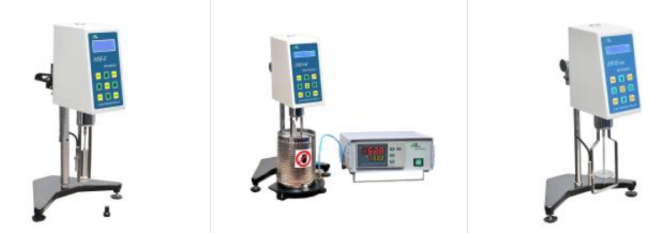
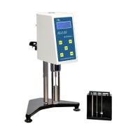
1. Take out the base, metal lifting rod, host, rotor frame, protective frame, power adapter, RTD temperature probe, etc. from the packing box.
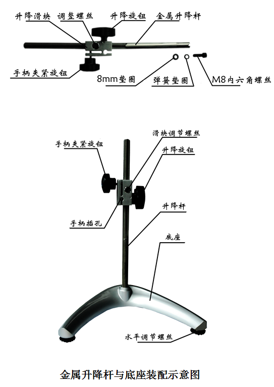
2. Insert the metal lifting rod into the middle hole of the base, align the notch at the bottom of the lifting rod with the slot in the middle hole of the base, and fix the lifting rod with M8 socket head screws and spring washers on the reverse side of the base. Tighten the M8 screws with a wrench. Screw the two level adjustment feet into the two ends of the base respectively, and the screwing distance should be as equal as possible.
3. Turn the knob on the lifting rod to check the flexibility and self-locking of the lifting chuck. If it is too loose or too tight, use a screwdriver to adjust the adjusting screw in front of the lifting rod so that it can go up and down. Automatic drop occurs when the viscometer is installed. Note: It has been adjusted at the factory.
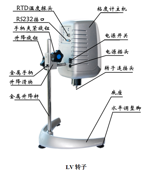
4. Insert the metal handle of the touch smart viscometer (hereinafter referred to as the viscometer) into the small round hole of the lifting slider, rotate the handle to clamp the knob , and at the same time adjust the position of the upper level of the viscometer so that the left and right positions are in the middle. Clamping the handle securely mounts the viscometer on the lift stand. Take off the black cap at the bottom of the instrument and put it aside for use ( it must be installed when the instrument is repaired and transported ) . The black cap is used to protect the connecting screw. When it is not used for a long time or transported, it must be covered with the black cap. 3. Turn the knob on the lifting rod or too tight, you can use a screwdriver to adjust the adjusting screw on the front of the lifting rod so that it can go up and down. Automatic drop occurs when the viscometer is installed. Note: It has been adjusted at the factory.
5. 调节二个水平调节脚 , 直至粘度计主机的水准器在中央位置。
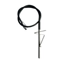
6. 将RTD温度探头,请安装到主机背面RTD温度探头接口。有微型打印机,请安装到 RS232 接口。
7. 确定粘度计的电源开关置于OFF 状态。连接电源适配器至粘度计上DC电源插座中。另外一端插入交流电源220V插座中。若要断开AC电源适配器,首先从电源插座上拔下AC电源插头, 然后从粘度计上拔下DC电源插头
粘度测试操作
(1) 按照使用前准备将粘度计安装到位。
(2) 将保护框架装在粘度计保护罩连接处 。( 向右旋入装上 , 向左旋出卸下 ) 。
(3) 将选用的转子旋入连接螺杆处 ( 向左旋入装上 , 向右旋出卸下 ) 。
(4) 开机。设置测试参数。
(5) 旋动升降架旋钮,使粘度计缓慢地下降,转子逐渐浸入被测液体当中,直至转子上的标记与液面相平为止。再一次调整粘度计位置至水平状态。
(6) 点一下“测量”键,即可同时测得当前转子、转速下的粘度值和百分计标度。
(7) 在测量过程中,如果需要更换转子,可直接点击“停止”键,此时电机停止转动,而粘度计处于不断电状态。当转子更换完毕后,重复以上第(5)至(6)条即可继续进行测量。
测试前的准备
A)粘度计:按照粘度计安装步骤安装到位,使用底座上的二个调节水平螺丝调整水平,并从粘度计前部的水平仪确认仪器是否达到水平状态,在每次检测之前或者检测过程中都要检测水平位置。
B ) 样品:被测流体(样品)需要放置在一个容器中,LV转子适合在400ml高型烧杯中(直径大于等于70mm)。我们为您建议特定的转子选择合适的容器。为了方便,您可要使用替换容器,但是这可能会对测量的精度产生一定影响。我们的粘度计用规定的容器进行校准。替换的容器得到的结果是可重复的,但是可能不是真实的标准粘度值。
LV转子是在装上保护框架情况下使用,没有保护框架的条件下进行测试可以得到可重复的结果,可能不是真实的粘度值。
当您和他人比较数据时,请确认使用的样品容器是否一致以及有没有使用保护框架,转子、转速是否一致,样品温度是否一致。
许多样品在测试粘度的时候需要控制特定的温度,当调节样品的温度时,也需要控制容器和转子的温度和样品一样。
C )转子、转速的选择:NTV-E系列测试粘度范围很宽,可以在1- 2M (M表示百万cP)的范围内测试流体,对于一种未知的流体,选择转子、转速的过程通常需要经过反复试验。合适的选择可以使粘度计扭矩范围在20%-100%之间。在反复试验过程中有二条通用规则:1)粘度范围与转子的尺寸大小成反比。2)粘度范围与旋转转速成反比。换句话说,测试高粘度,要选择体积小转子和低转速。如果选择的转子、转速使扭矩读数高于100%,则需要降低转速或选择更小转子。当试验证明几种转子、转速组合都可以符合测试效果时,在这种情况下,可以选择这几种转子中任意一种。
非牛顿流体测试得到的粘度会随着转子、转速的改变而改变。
要比较粘度数据,请确保使用相同的测试方法,即:使用相同的仪器、转子、转速、容器、温度以及测试时间。
注意事项
(1) 装卸转子时应小心操作,装卸时应将连接螺杆处微微抬起进行操作,不要用力过大,不要使转子横向受力,以免转子弯曲。
(2) 请不要把已装上转子的粘度计侧放或倒放。
(3) 连接螺杆与转子连接端面及螺纹处保持清洁,否则会影响转子晃动度。
(4) 粘度计升降时应用手托住,防止粘度计因自重而下落。
(5) 调换转子后,请及时输入新的参数。每次使用后对换下来的转子应及时清洁(擦干净)并放回到转子架中。请不要把转子留在仪器上进行清洁。
(6)当调换被测液体时,请及时清洁(擦干净)转子和转子保护框架,避免由于被测液体相混淆而引起的测量误差。
(7)仪器与转子为一对一匹配,请不要把数台仪器及转子相混淆。
(8)请不要随意拆卸和调整仪器零件。
(9)搬动及运输仪器时,应将黑色盖帽装在连接螺杆处,放入铝合金包装箱中。
(10)装上转子后,请不要在无液体的情况下长期旋转,以免损坏轴尖。
(11) Many of the suspensions, emulsions, polymers and other high-viscosity liquids are "non-Newtonian liquids", and their viscosity values change with changes in conditions such as shear speed and time. The inconsistency of the measured results under the speed and time is normal and not an instrument error. For the measurement of non-Newtonian liquids, the rotor, rotational speed and time should generally be specified.
(12) Doing the following points will help to measure more accurate values:
• Accurately control the temperature of the measured liquid.
• Immerse the rotor in the liquid to be measured for a long enough time to make the temperature of both the same.
• Maintain liquid homogeneity.
• When measuring, place the rotor in the center of the container and be sure to install the protective frame.
• Keep the rotor clean and free from vibration.
• When the measurement of high rotation speed changes to low rotation speed immediately, the measurement should be stopped, or the measurement time at low rotation speed should be controlled a little longer, so as to overcome the error caused by the liquid rotation inertia.
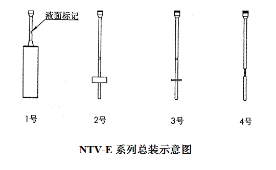
• Use spindle #1 for low viscosities and spindle #4 for high viscosities.
• When measuring viscosity at low speed, the measurement time is relatively long.
• During the measurement process, due to the need to change the rotor, the liquid to be measured, etc., after changing the position of the viscometer by rotating the lifting chuck, check and adjust the horizontal position of the viscometer in time.
• Maintain good AC power grounding to eliminate internal circuit damage caused by static electricity.
• Please note: During the operation, it is strictly prohibited to gradually immerse the rotor into the sample when the rotor is rotating, especially for high-viscosity samples, so as not to damage the internal structure of the instrument and cause measurement errors.