Working principle and usage
The new touch screen viscometer is an intelligent instrument based on ARM technology, which realizes full touch screen operation in CHINA, replacing traditional operation mode of buttons and small LCD screen. This series of viscometers adopts high-performance stepping motors and drivers to run accurately and smoothly according to the program settings. The motor drives the rotor to rotate at a constant speed through the torque sensor. When the rotor is subjected to viscous resistance in the measured liquid, the force is fed back to the torque sensor, and after corresponding internal processing and calculation, the viscosity data of the measured liquid can be displayed. Compared with similar instruments, this series of instruments has the advantages of convenient operation, intuitive reading, rich display content, high measurement accuracy, stable speed, strong anti-interference performance, and wide working voltage [110V~240v, 50/60Hz]. In terms of instrument operation and use, this series of instruments has the function of the measured value accounting for 100% of the full scale value, the alarm display , and the automatic scanning function. Relying on these, the user can intuitively, quickly and accurately select the appropriate available rotor and speed combination, and can save the determined test conditions so that they can be quickly recalled and used in the production test process in the future.
This series of instruments are widely used in solvent-based adhesives, latex, biochemical products, paints, coatings, cosmetics, inks, pulp, food, and other industries.
Environmental conditions
Ambient temperature: 5°C-35°C (recommended ambient temperature around 20°C) Relative humidity: ≤80% Power supply: AC100-240V (50/60Hz) There is no strong electromagnetic interference, no corrosive gas, and no violent vibration near the instrument.
Instrument installation
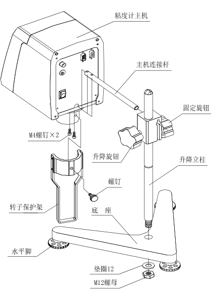
1. Take out the base, lifting column, viscometer . As shown in Figure 1, insert the lifting column into the base hole and tighten it with the nut (note: the lifting knob is placed on the right side), turn the lifting knob to adjust to the appropriate lifting tightness, so that the host will not automatically slide down, And when lifting, the damping feel should be . If it is too loose or too tight, it can be adjusted through the adjusting screw in front of the lifting slider.
2. Unscrew the screw on the connecting rod of the main unit, and then insert the milling plane down into the mounting hole at the rear and lower part of the main unit, and connect and fasten the connecting rod of the main unit to the bottom plate of the main unit with the unscrewed hexagon socket head screws . Then insert the host machine with the connecting rod into the installation hole of the lifting slider, and tighten the fixing knob after straightening.
3. By adjusting the three leveling feet under the base, make the level bubble in front of the instrument be in the center of the black circle.
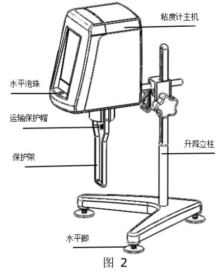
4. Take off the transport protection cap under the instrument cover, and turn on the power of the instrument. The appearance after assembly is shown in Figure 2.
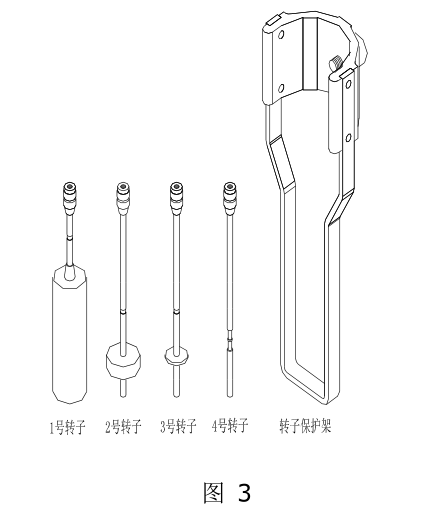
5. The structures of No. 1~4 rotors and rotor protection frame that come standard with the machine are shown in Figure 3.
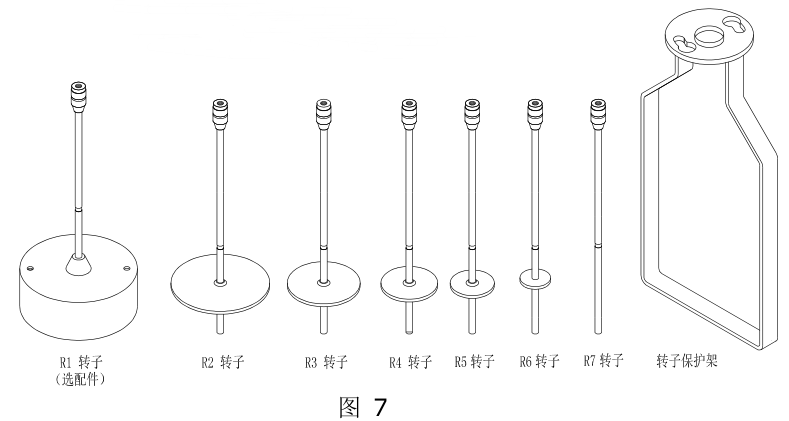
6. The structure of No. 1~4 rotors of standard configuration of NDJ/SNB/LVDV series viscometer is shown in Figure 3. The structure of R1~R7 rotors of RVDV/HADV/HBDV series viscometers is shown in Figure 7. The R1 rotor is an optional accessory, and the HA/HB series viscometers are not equipped with a rotor protection frame.
7. How to install and use No. 0 rotor (this part is optional)
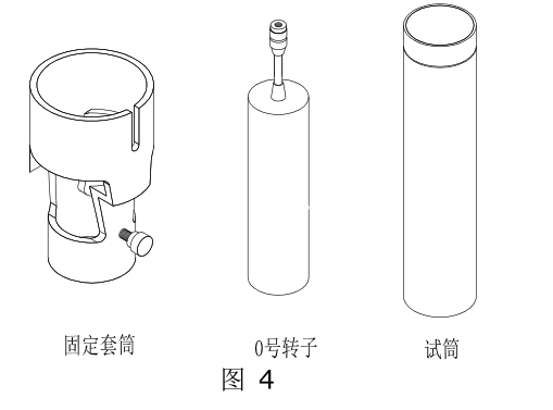
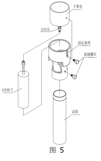
⑴ The No. 0 rotor part is composed of a fixed sleeve, a No. 0 rotor and a test cylinder. Its structure is shown in Figure 4. This part can only be used for the No. 0 rotor measurement, and it is not suitable for other rotor tests.
⑵ The installation of No. 0 rotor is as shown in Figure 5. First, rotate the No. 0 rotor clockwise (reverse thread) and install it on the rotor connecting screw (universal head).
⑶ Put the fixing sleeve on the cylinder of the lower cover at the bottom of the instrument from bottom to top, be careful not to touch the No. 0 rotor, and tighten it with the sleeve fixing screw.
⑷ Pour 20mL of the fluid to be tested into the test cylinder.
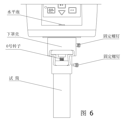
⑸ 将装有流体的试筒由下往上轻轻地套入固定套筒直至上升到最上面,并用试筒固定螺钉予以并紧(注意试筒装入时不要碰到 0 号转子),旋紧时需要注意试筒固定螺钉之锥形端以旋入试筒外壁上端之三角形槽内。全部安装好的 0 号转子部件如图 6所示,控制好被测液体温度,调整好仪器水平状态后即可以进行测试。
⑹ 注意 0 号转子使用时不可在没有流体装入时进行空载旋转,0 号转子使用时不用装转子保护架。
SNB-1A-T 粘度计转子的安装步骤
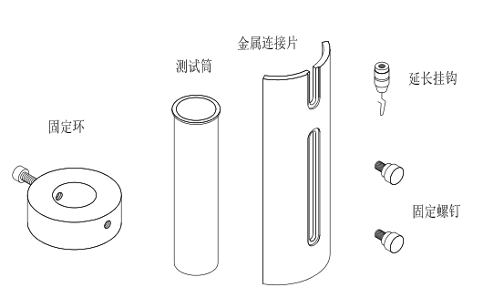
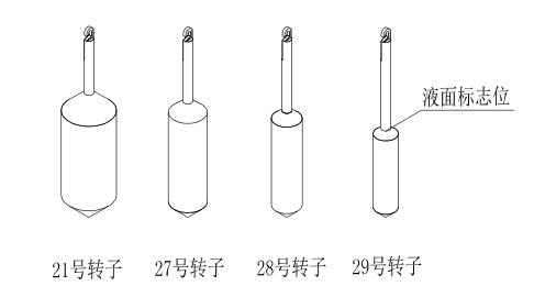
⑴ SNB-1A-T 粘度计转子部件是由固定环、测试筒、金属连接片、延长挂钩、固定螺钉及21、27、28、29 号四个转子组成,见图 8 所示。
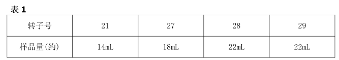
⑵ 准备好被测试样品,有条件可以控制被测液体的温度。According to所选的转子倒入适量(见表1)的被测样品于测试筒内。
⑶ 按图 9 所示将转子延长挂钩 顺时针 (反螺纹)旋入万向接头,According to样品粘度范围选好使用的转子挂上。
注意 :装 卸转子延长挂钩 时 需要微微向上托起万向头 , 防止损坏转动轴尖

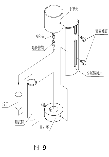
⑷ 将测试筒放入固定环中,并拧紧固定环侧面螺钉。
⑸ 用固定螺钉将装好的固定环与金属连接片相固定。
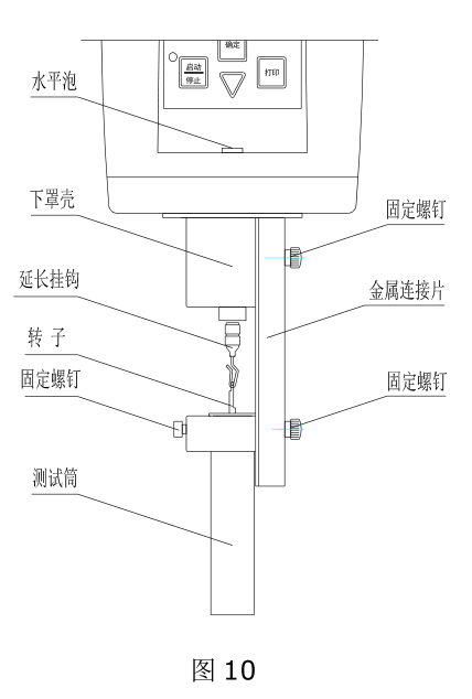
⑹ 再将装好的金属连接片与粘度计主机下罩壳用固定螺钉固定。安装好的部件见图 10 所示。
⑺ 调整转子浸入的深度,使液面刚好与转子的“液面标志位”持平。液面标志位以转子的锥体最上端为准。详见图 8。
⑻ 再次调整好仪器水平,使水泡处于中间。
⑼ 选择确认好合适转速按运行键即可直接测试粘度值。
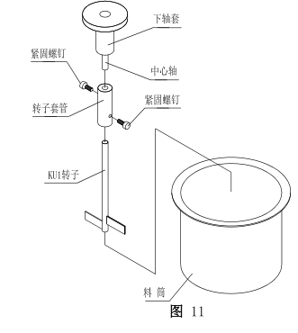
STM-2T 粘度计转子的安装步骤
(1)将转子及转子套管从包装盒内取出,并用紧固螺钉固定转子。注意:紧固螺丝应固定在转子杆的扁口上,将转子套管另一端用紧固螺钉固定在中心轴。在料筒内倒入适量的被测样品。具体详见图 11
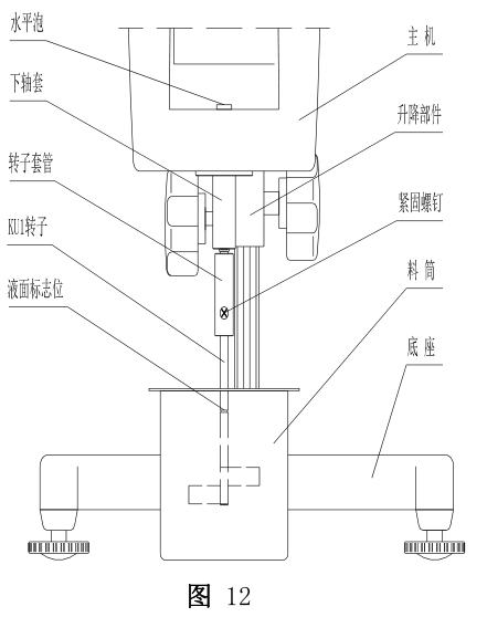
(2)拧动升降旋钮使仪器缓缓下降,将转子浸入样品内且转子上的液面标志位( 转子杆上 的 凹槽 或 凸线)与被测液面保持平齐。具体详见图 12
(3)再次检查仪器前方水平仪是否在水平状态。
(4)确认无误后点击运行键即可直接测试粘度值。
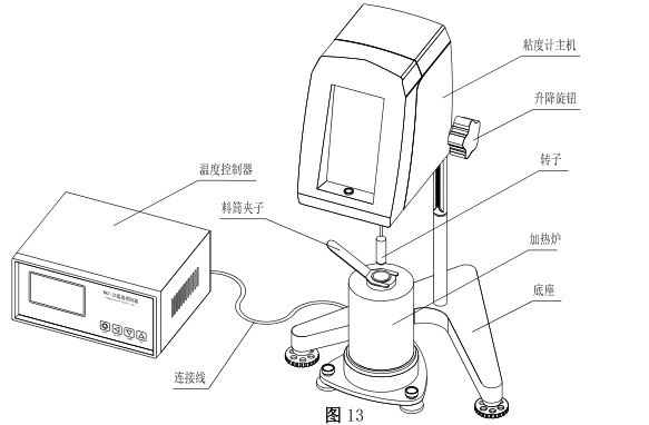
10.NDJ-1C-T/SNB-1J-T 粘度计安装介绍
(1)将机器各部件从包装箱内取出,参照上文“仪器安装”介绍,将粘度计主机与底座安装好。
(2)把加热炉安置在粘度计主机的下方,调整加热炉底座水平脚,使加热炉底座水平泡中的水泡位于中央,调整完成后并拧紧水平脚紧固螺母。
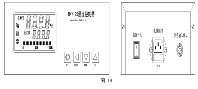
(3)把加热炉引线对应插入温度控制器后盖信号输入端口,安装完成的外形详见图 13。 (引线插进去时请注意方向,将突出槽对应相应位置才能插入连接上。)NKY-25 温度控制器正反面图详见图 14 说明
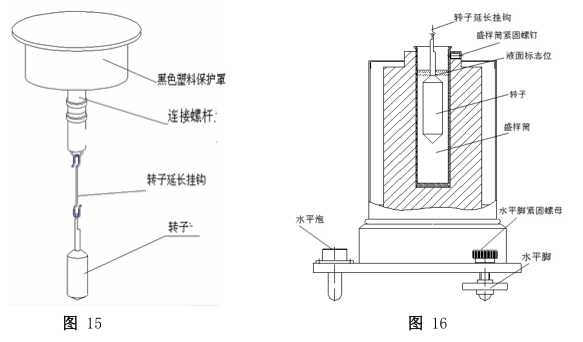
(4)取下粘度计主机下方转轴塑料保护帽,将转子延长挂钩 顺时针 (反螺纹)旋入万向接头,According to样品粘度范围选好使用的转子挂上。详见图 15 说明
(5) According to the selected rotor, take the corresponding measured sample amount (see Table 1 for details) and put it into the barrel (it can be converted into mass according to the density of the sample) to avoid sample overflow or insufficient amount. When the sample is initially used, the state of the sample is fluid enough to insert the rotor into the sample. At this time, please insert the selected rotor into the sample together. If the sample is solid or paste-like when first used , the rotor cannot be inserted into it. Insert the rotor when the temperature rises and the sample begins to melt . If conditions permit, put the rotor in an oven to keep the temperature near the set temperature, and when the sample temperature reaches, hang the rotor on the extension hook with needle-nose pliers and insert it into the sample for testing.
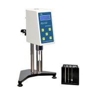
(6) After the rotor is placed in the sample, check whether its liquid level mark (see Figure 16 for details) is appropriate, and the rotor can be adjusted to a suitable height by lifting the knob.
(7) When the test is completed, use a special handle to take the sample cylinder out of the inner hole of the heating furnace. Please be careful not to burn yourself.