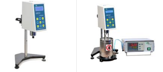
11. NKY-25 temperature controller instructions
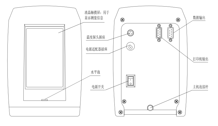
(1) Figure 14 shows the front view of the temperature controller, the liquid crystal display on the left is the temperature display area, and the right end is the temperature setting area.
"Measured value" The current actual temperature value in the sample cylinder.
"Setpoint" Pre-set target temperature value.
"SET" This key is used to modify the set value and confirm the function of modifying information.
"SHIFT" Shift key, used to move digits when modifying parameters.
"DOWN" When the parameter is modified, the corresponding set value will decrease by 1 each time it is pressed.
"UP" When the parameter is modified, each time it is pressed, the corresponding set value will increase by 1.
(2) The vertical square display below the set value represents the percentage of heating power output by the machine, and the larger the percentage value, the greater the heating power. The size of the heating power is automatically controlled by the machine. In principle, the greater the difference between the measured value and the set value, the greater the output heating power of the machine; and vice versa.
(3) "Power switch" is used to control the power on and off of the temperature controller.
"Power socket" integrates the power fuse of the temperature controller and the power socket together.
"Signal input port" is connected with the lead wire of heating furnace
(4) Temperature controller parameter setting
Heating temperature setting: In the standby state of the instrument powered on, press the "SET" button once, and the displayed value will display "SP" (indicating entering the temperature setting state), and the last digit on the set value display will flash. Then press the "DOWN" key or "UP"
key and "SHIFT" key to set or modify the required heating temperature parameter value. After setting, press the "SET" button to confirm the set temperature value, and enter the time setting at the same time.
Heating time setting: In the standby state of the instrument powered on, press the "SET" key twice, and the display will display "ST" (indicating entering the time setting state), then press the "DOWN" key or "UP" key and "SHIFT" key to set or modify the required heating time parameter value. After setting, press the "SET" button to confirm the set time value, and the display will return to the standard display state.
Note: ? Each time the "SET" key is pressed, the display will cycle between temperature setting (SP) → time setting (ST) → return to the standard display state.
After setting the parameters, you need to press the "SET" button to confirm the set value, otherwise the set value will not be saved.
The set time starts counting when the temperature of the heating box reaches the set value. After the timing is completed, the temperature controller will sound an alarm and the "set value" will display EDN.
Preparation
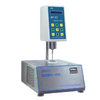
1. Using NDJ/SNB/LVDV series viscometer, pour the tested sample into a circular flat-bottomed container with a diameter not less than 60mm. Use RVDV/HADV/HBDV series viscometers, the diameter of the sample container should not be less than 100mm.
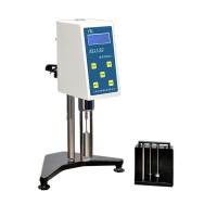
2. Attach the rotor protection bracket to the silver cover under the instrument. (Installation method: Put the two round holes at the upper end of the protective frame into the fixed shaft of the lower case, and then turn it counterclockwise)
3. Select the applicable rotor, and screw it clockwise (reverse thread) to the lower shaft joint.
4. Turn the lifting knob to lower the instrument slowly, immerse the rotor into the sample and keep the liquid level marking line (groove or convex line on the rotor rod) level with the measured liquid level.
5. Check again whether the spirit level in front of the instrument is level.
Note: When loading and unloading the rotor, do not pull the shaft joint downward or laterally to avoid damage to the internal structure. During the test, the ambient temperature needs to be constant to ensure the stability and accuracy of the measured value.
Instrument operation interface description and operation
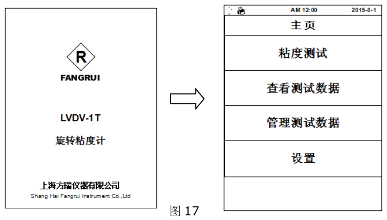
Take the LVDV-1T model as an example: after starting up, the instrument first displays the initial interface, and then automatically enters the main menu page (Figure 17) after waiting for 3 seconds . There are 4 options in the main menu:
Viscosity test: measure the viscosity value of the sample;
View viscosity data: read and print the saved test results;
Manage viscosity data: export or batch delete the saved test results;
Setting: Setting of the basic parameters of the instrument, such as: time, date, storage path, factory reset, language selection, screen backlight adjustment, etc.
1. Viscosity test
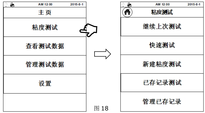
1.1 点击 “ 粘度 测试”进入粘度测试界面(图 18),该界面内共 5 个选项:
继续上次测试:使用上一次(断电前)的测试条件继续测试
快速测试: 快速进行粘度的测定,只需选择转子、转速,测试完成后数据无法保存
新建粘度 测试:新建一个测试记录测试
已存记录测试:调用已存储的记录测试
管理已存记录:删除已保存的测试条件
1.2 According to不同测试需求点击“ 继续上次测试”、“快速测试”、“新建 粘度 测试”中的一项,以 “新建 粘度 测试”为例,点击后进入参数设置界面(图 19)
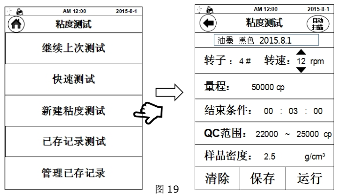
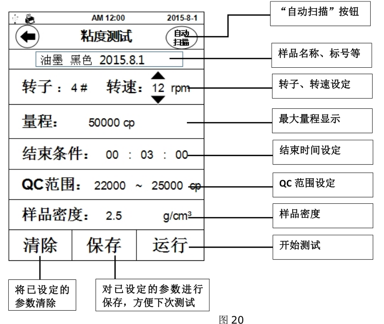
1.3 参数设置:在粘度测试前要先设定好适合被测样品的测试参数(图 20),其中“ 样 品 名称”、“转子”、“转速”为必填项, “结束 时 间”、“QC 范围”、“样 品 密 度 ”为选填项。转速设定是通过数值上、下的箭头进行选择,其余参数都是点击参数值后使用虚拟键盘输入。
例 : 如已 知 被测样 品粘度 值约为 为 3000mpa.s , 则可 选 择下列组合 :
2# 转子 、6rpm;或 或 3# 转子、30rpm参数设定完成后可以将参数存入内置储存中,在下次的测试中即可通过“ 继续上次测试”直接使用该参数进行粘度测试。也可在日后的使用中从“ 已存记录测试”中调取该组参数进行测试。
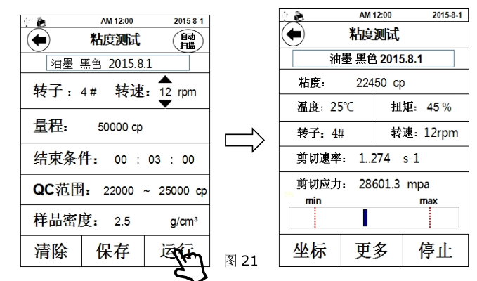
1.4 开始测试:参数设置好后,点击“ 运 行”开始测试,界面切换至测试界面(图 21),
粘度: 被测样品的粘度值(若测试时显示 ERROR,表示超出量程需更换表更大量程)
温 度: 温度传感器所测得的温度值(需选配温度传感器才能显示温度值)
扭矩: 测量值与满量程的百分比
转子: 当前所选的转子号
转速: 当前所选的转速(RVDV/HADV/HBDV 系列粘度计转速可以无级调整,即不停止
运转情况下改变转速)
剪切速 率: 当前测试条件下的剪切速率
剪切应力: 当前的剪切应力
条状趋势栏:扭矩趋势栏,刻度代表当前扭矩百分比,两端红色虚线处分别代表 10%和 90%
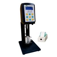
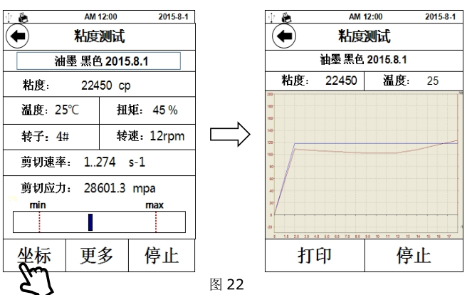
1.5 测试时点击“ 坐标”,显示界面会从列表显示变为坐标系显示状态(图 22),如需返回列表界面请点击左上角 图标,点击“ 打印”可将当前测试数据及坐标曲线通过外置打印机打印出来(需选配专用外置打印机)。
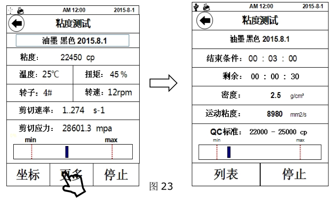
1.6 测试时点击“ 更多”,该界面显示内容为之前的可选参数(图 23),如测试前未设置则无显示。
结束条件:设定一个时间段,从开始测试时,到达时间后测试自动停止,此时数据依然留在测试界面,此功能在测试如剪切变稀的非牛顿流体时较为实用
剩余:剩余结束时间
密度: 测试前填入的被测样品的密度 ,用以换算运动粘度
运动粘度: 被测样品的运动粘度值
QC 标准: 预设定一个粘度范围,用于判定所测得粘度值是否符合该样品的粘度标准,下
方趋势栏则对应该范围,两端红色虚线分别对应最小值与最大值。例:下图中样品粘度标准为 22000cp~25000cp,实测粘度值为 22450cp,趋势栏刻度线处于红色虚线内,则认定该样品符合标准。该功能能便于生产中对多种样品的品控管理
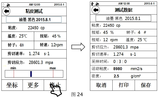
1.7 结束测试:完成测试后点击“ 停 止”,进入测试数据界面(图 24),点击“ 打印”可将测试数据通过外置打印机打印出来,点击“ 保 存”可将测试记录储存到仪器内存中,可在主菜单“ 查看 粘度 数据”一项中调阅并打印,保存前需要输入样品名称,否则保存无效。
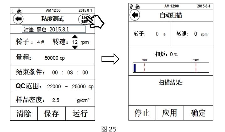
1.8 自动扫描:该功能可为操作者提供很好的的转子、转速组合信息。点击参数设置界面右上角的 “ 自 动 扫描” ”,界面切换至扫描界面(图 25),设定任一转子,同时装上该型号转子,点击“确定”开始扫描,“扫描结果”一栏中开始显示扫描状态,当扫描结果满足测试要求时,“扫描结果”处显示“合适”,点击“应用”直接把扫描结果应用到测试参数中。如扫描结果无法满足测试要求时,“扫描结果”处显示“请更换小号转子”或“请更换大号转子”,此时按照屏幕提示操作即可。
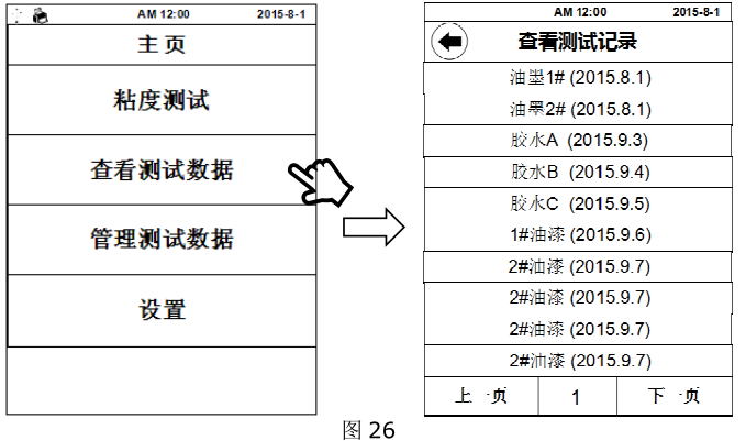
2、查看、打印测试记录:点击“查看测试数据”后,屏幕上会显示已存储的测试记录(图 26),选择所需的记录查阅或打印。
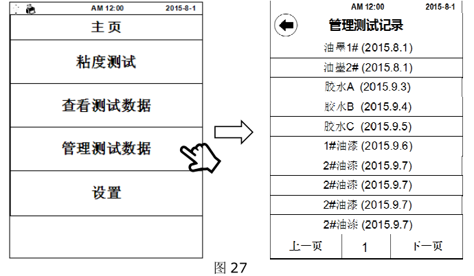
3、管理测试记录:点击“管理测试数据”后,屏幕上会显示已存储的测试记录(图 27),选择所需的记录即可删除该项记录。
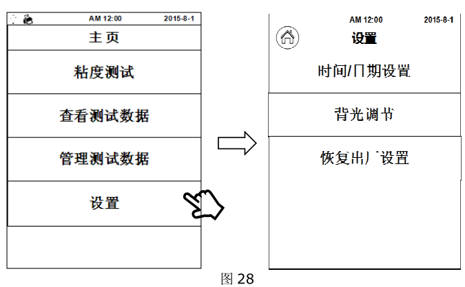
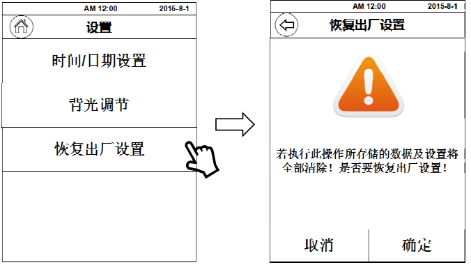
4、设置:仪器的常规设置,时间、日期等 (图 28)
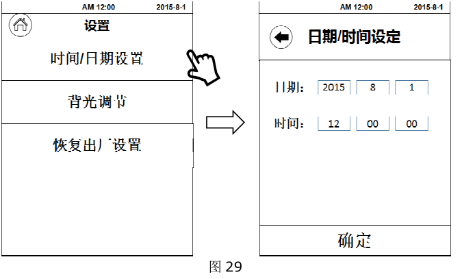
4.1 时间、日期的设定:点击“ 时 间/ 日期 设 置”,直接对日期、时间栏中的数值进行调整。(图 29)
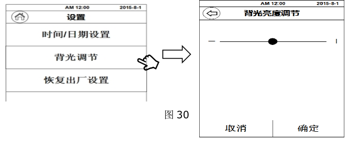
4.2 背光调节:点击“ 背光调节”,通过指示条两端的“-”“+”或直接拖动圆形调节钮进行屏幕亮度的调节。(图 30)
4.3 恢复出厂设置:点击 “ 恢复出厂 设 置” ”,出现右图界面,此时如果点击 “ 确 定” ”,仪器将恢复到出厂时的状态,仪器内存储器中的测试记录和参数记录也将会被清除。(图 31)
5、STM-2T 机型操作界面介绍
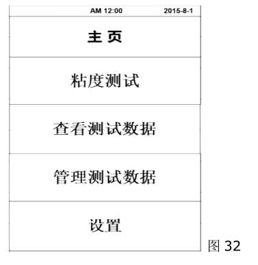
开机后仪器首先显示初始界面,等待 3 秒钟后自动进入主菜单页面(图 32),主菜单共
有 4 个选择条:
粘度测试: 对样品进行粘度值的测量;
查看粘度数据:对已保存的测试结果进行调阅、打印等操作;
管理粘度数据:对以保存的测试结果进行导出或批量删除等操作;
设置: 仪器的基本参数的设置 ,如:时间、日期、保存路径、恢复出厂设置、选择语言、调节屏幕背光等。
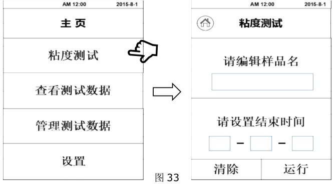
5.1、 粘度测试
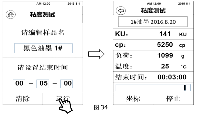
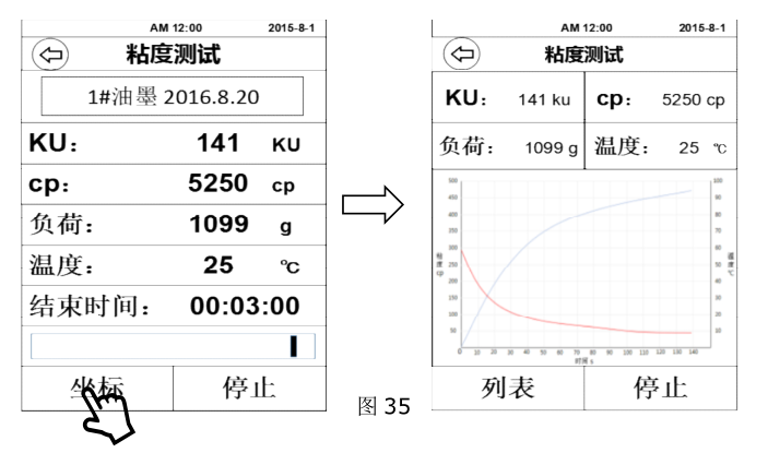
点击“粘度测试”进入粘度测试界面(图 33),首先输入样品名(中/英文、数字皆可),然后设置测量时间(时-分-秒),设定完成后点击“运行”即可开始测试粘度。
开始测试:开始测试后进入粘度测量界面(图 34),该界面中可直接读取所测得的该样品的各种数值。在测试过程中,点击“ 坐标”会进入坐标曲线界面(图 35),该页面中的数据会以曲线的形式在一个坐标系中显示。测试完成后点击“ 停 止”则完成测试或运行到设定测量时间结束时自动停止测试。如样品的粘度值过大,仪器会有溢出警告,此时 KU、CP、负载值都会显示 ERROR,此情况则说明该测试样品的粘度值已经超出了本仪器的最大量程。
对于未知样品的粘度测量,首先应估算样品的粘度值。再选择相对应的几组转子、转速组合来进行测量。当估计不出被测流体的大致粘度值时,应假定该样品的粘度值较高,用由小到大(体积)的转子和由慢到快的转速进行测试。粘度 测 量 的原 则 是: 高 粘度的 流体 选用 小 ( 体积 ) 的 转子、 慢转速 ;低 粘度的 流体 选用 大 ( 体积 ) 的 转子、快转速 。
注意事项
1. 由于粘度是温度的函数,仪器在常温下工作时,温度波动应控制在±0.1℃,否则会影响测量的准确度,必要时可选配恒温浴槽控制温度。
2. 保持转子表面清洁。
3. Since the hairspring has a certain linear region, please pay attention to the torque percentage when measuring, and the value should be between 10% and 90%. When the value of the opening angle percentage is too high, the torque and viscosity will display the overflow symbol "ERROR", At this time, the rotor should be replaced or the rotating speed should be changed, otherwise the measurement accuracy will be affected.
For example: if the LVDV-1T test sample is tested with the "No. 1 rotor, 60 revolutions per minute" speed combination test, and the torque percentage shows "ERROR", then the speed should be reduced. If the torque percentage still shows "ERROR" when it has been reduced to "0.3 revolutions per minute", then a smaller rotor (smaller surface area) should be used for testing. For example, when the tested samples are in the same rotor condition, the torque percentage values at different speeds are all between 10% and 90%. Then take the larger value of the torque
This operation manual is common to all models of viscometers, please read according to the machine model or configuration you purchased! shall prevail, and so on for other models.
4. Be careful when loading and unloading the rotor, lift , and do not use too much force. Do not force the rotor laterally and never pull the rotor down to avoid damage to the shaft tip. Since the connection between the rotor and the universal joint is a left-hand thread, please remember the direction of rotation (as shown in the figure on the right) when loading and unloading the rotor , so as not to damage the universal joint.
5. The instrument should be lowered slowly, and it is better to hold it by hand to avoid damage to .
6. When the instrument is being transported or moved, the rotor connector should be covered with a plastic protective cap.
7. Many suspensions, emulsions, polymers and other high-viscosity liquids are "non-Newtonian" liquids, and their apparent viscosity values change with shear speed and time, so in different It is normal for the results to be inconsistent when measuring with the same rotor, rotating speed and time. (If non-Newtonian fluid is measured under the same rotor and different rotating speed; the results will also be biased.) This is determined by the nature of the fluid, not the instrument There is a problem with the test.