Both color instruments and software packages contain references to CIE standard illuminants and observers. What do these terms mean, and how are they used in actual color evaluation? The CIE (from the French Çommission i internationale de l'ē clairage), or the International Commission on Illumination, is the global credence for how we see and measure color. BYK-Gardner uses many of these standards in its instruments and available software packages .This article will provide some easy-to-understand explanations of these standards and how to use them.

standard observer
In 1931, it was shown that most of the cones located in the human eye are located in a rather small area at the back of the eye, defined by a 2 degree angle of incidence at the fovea. A small group of human observers start with a set of red, green and blue lights, looking through a pinhole-type device, to match a set of colors. The viewing angle is set at a 2-degree angle, which activates the known color receptors in the eye. Thus was born the 2-degree Standard Observer.
However, in 1964, this standard observer was modified to include foveal stimulation at a 10-degree angle. The cones were found to be much larger than previously thought. This 10 degree viewing angle is now believed to provide a good average spectral response for a human observer. However, certain industries and conditions still designate 2-degree observers. Often a 2 degree observer is better used for color evaluations where the sample being tested is often at a distance (e.g. road signs) or the length of a dime (when printing).
standard light source
This would account for the 2 and 10 degree lighting angles. But what about the letter codes found before the "/" symbol in the light source and observer combination? These all refer to the mathematically defined spectral power distribution of many artificial light sources or light sources.
The first illuminants defined by the CIE were the A, B, and C illuminants defined in 1931. The "A" light source is defined to represent the average incandescent light source or tungsten bulb. The "B" and "C" light sources were then defined using liquid filters to represent direct midday sunlight with a color temperature of 4874K (B) and average sunlight of 6774K (C). B is no longer used, and is rarely even mentioned in the specification. Although the C illuminant is not an official CIE illuminant, it is still often referred to. It was loosely defined by the CIE, but never achieved "Standard Illuminant" status.
In the years following these initially defined light sources, many others have been defined. Most are light sources that are theoretically described mathematically and cannot be found anywhere in real life. But they are useful because they provide a standard of comparison and are closely related to the light in our environment and how it changes the appearance of physical samples.
After the A, B and C groups of lights is the Daylight group of lights. None of these illuminants were found in nature, but the spectral power distributions used to characterize these various illuminants were derived from three vectors. The first is the average of all SPD factors and is used to reconstruct the SPD with only one fixed vector. The second vector corresponds to the yellow-blue shift caused by the change in correlated color temperature caused by the presence or absence of direct sunlight or clouds. The third vector corresponds to the pink-green color change caused by the presence of water as a vapor or mist.
These D light sources are named according to the color temperature they are intended to simulate. For example, the D50 is used as a Horizon Light emulator with a color temperature of 5000 Kelvin. D55 is used for morning light with a color temperature of 5500 Kelvin. D65 is for midday sunlight and has a temperature of 6500° Kelvin. Finally, D75 corresponds to northern daylight at 7500° Kelvin.
All four of these 3D sources have their own industry supporters and are used in the definition of standards. For example, the paint industry typically specifies illuminant/observer as D65/10°. The printing industry typically specifies D55/2°. Knowing the standard illuminant and observer angle is very important when comparing instrument measurements and deltas. Using the wrong combination can result in misleading/erroneous measurements and approval of substandard material.
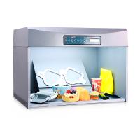
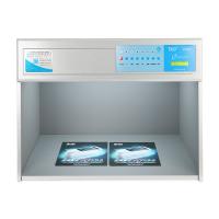
Nowhere are these distinctions more pronounced and vendor-specific than in the fluorescent lighting industry.
There are at least 8 different fluorescent lamps to match the spectral output of bulbs from various manufacturers. However, manufacturers match bulbs to each other, and even though the color temperature may be equal, the set of phosphors used to create that temperature may vary between manufacturers and result in large differences in spectral peaks and valleys when evaluated with a spectroradiometer. big. The various fluorescent lamp types are listed here:
F4 is known as Warm White Fluorescent (WWF) and is used to closely match the temperature of an incandescent bulb in a domestic environment.
F6 is a fluorescent lamp with a temperature of 4150° Kelvin. F6 tubes are often called cool white fluorescent lamps.
F7 bulbs are daylight fluorescent (DLF) with a color temperature of 6500° Kelvin.
The F8 bulb has a color temperature of 5000°K, very similar to the D50 light source above.
F10 – F12 fluorescent tubes are known as narrowband tubes – the spectral power is limited to a few peaks. Images courtesy of BYK-Gardner.
F10 – F12 fluorescent tubes are known as narrowband tubes – the spectral power is limited to a few peaks.
F10 bulbs also have a color temperature of 5000°K. However, they differ enough from F8 light sources to warrant their own spectral characteristics.
F11 bulbs are also known as T84 or TL84. These are energy-saving fluorescent lamps with a very narrow spectral lighting band.
So after reading about all these light sources, the obvious question is "what does this mean to me, and why is it important to know which light source to use?" The L*a*b* color values are derived from the sample spectral curve and the light source spectral values combination. A sample may look completely different under two different light sources. However, individual samples always look the same to the human eye -- which has supercomputer intelligence in compensating for various external light sources. However, when evaluating two different samples that may have slightly different pigmentation, the illuminant will play a huge role in how the two samples will appear relative to each other. Consider an orange sample evaluated in daylight at about 5000°K. A second sample with slightly different pigmentation may look the same in real sunlight at about 5000°K. However, under an F10 fluorescent bulb (also a source of 5000°K), much of the light in the 550 will be reflected from the sample - the 600 nm range and beyond 625 nm are missing. The L*a*b* values will be very different, and metamerism is very likely.
Samples may look the same in real daylight. Under cool white fluorescent lighting, they may look the same. They may look the same under an incandescent light bulb. But then you walk into an area with energy efficient F10 bulbs and they just look like a completely different color. Mathematical values used in Spectral Guide's firmware and most color evaluation software (such as BYK-Gardner's auto-QC) help determine whether a color will match under the various lighting conditions a sample may be subjected to.
Know the light source requirements and use it. This is how you guarantee a good color match that doesn't change when you change the lighting around you.