Surface profile is defined as a measure of the maximum peak-to-valley depth produced by abrasive impact on a surface during a blast cleaning operation or by impact-type power tools. During the blast cleaning process, kinetic energy is generated by the mass of the abrasive and the velocity at which the abrasive is moving through the compressed air (the abrasive can reach speeds of over 600 miles per hour as it exits the nozzle). When the abrasive hits the surface, it cuts into the surface (angled abrasive) or peens the surface (round abrasive) and creates a series of peaks and valleys across the surface.
Forming this pattern of peaks and valleys on the surface effectively increases the surface area, providing anchor points for the coating system. During use, both the structure and the coating system protecting the structure move. This movement may be due to expansion and contraction of the substrate due to temperature fluctuations, or due to live loads applied to the structure. For example, traffic across a bridge. The surface profile needs to be compatible with the coating system. In general, the higher the coating thickness, the greater the depth of the surface profile. Peak density (number of peaks per unit area) also plays a key role in maintaining adhesion of the coating system and can provide greater resistance to corrosion undercutting should the coating system become damaged in service.
Surface Profile Measurement Standards
There are currently four main standards for measuring the surface profile of steel surfaces. Note that ASTM D4417 and SSPC-PA 17 also address the measurement of surface profiles produced by impact-type power tools. The four criteria are:
ASTM D4417, Standard Test Method for Field Measurement of Surface Profiles of Blast Cleaned Steel;
ASTM D7127, Standard Test Method for Surface Roughness of Blast-Cleaned Metal Surfaces Using a Portable Stylus;
NACE SP0287, In-Situ Measurement of Surface Profile of Blast-Cleaned Steel Surfaces Using Replica Tape; and
SSPC-PA 17, Procedure for Determining Compliance with Steel Profile/Surface Roughness/Peak Count Requirements.
How is surface profile depth quantified?
ASTM D4417 contains three methods for measuring the depth of a surface profile: Method A describes the proper use of a comparator; Method A describes the proper use of a comparator. Method B describes the use of a depth micrometer and Method C addresses the use of replica tape (as does NACE SP0287). Method B and Method C are common methods these days, so we'll focus on that.
ASTM D4417, Method B
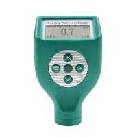
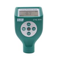
Method B in the ASTM standard describes the use of a depth micrometer. Surface profile depth micrometers use a 60° conical point protruding from the base of the gauge to measure the depth of surface profile valleys relative to the height of the peaks. The base of the instrument rests on the peaks of the surface profile, while the tapered points protrude into the valleys. Depth is indicated on the gauge in mils (0.001") or microns (0.001mm; 1 mil has 25.4 microns [µm]). This method can be used to measure the depth of surface profiles produced by blast cleaning or impact power tools. Models of some gage manufacturers conforming to this standard are available.
According to ASTM D4417, obtain at least 10 readings per area. Reports the largest surface profile (discarding obvious outliers). SSPC-PA 17 states that at least three 6" x 6" areas are to be measured per work shift or 12 hours of prep work, whichever is shorter. Measurements are required to meet the minimum and maximum surface profile requirements listed in the project specification.
ASTM D4417 Method C
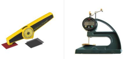
Method C in the ASTM standard describes the use of duplicating tape. By pressing the polyester film with an abrasive tool under moderate pressure, a mirror image of the peak-valley pattern produced by blast cleaning was created in the emulsion foam applied to the underside of a 2 mil polyester film (Mylar®). After the polishing process is complete, the replica tape is removed from the surface and the image is measured using a spring-loaded micrometer.
Subtracting the thickness of the mylar (2 mils) from the measurement reveals the depth of the surface profile inside the area being measured (approximately 3/8 inch in diameter). Alternatively, a replica tape reader (RTR) can be used to read a replica tape.
According to ASTM D4417, at least 2 readings were obtained for each area. The average of two readings is reported. SSPC-PA 17 states that at least three 6" x 6" areas are to be measured per work shift or 12 hours of prep work, whichever is shorter. Measurements are required to meet the minimum and maximum surface profile requirements listed in the project specification.
Same surface, different results?
When project specifications refer only to ASTM D4417 rather than a specific method, the results of surface profile measurements may will vary. Control inspectors are using replica tape, while the facility owner's quality assurance inspectors are using depth micrometers. While the depth micrometer and replica tape methods both comply with ASTM D4417, the principles of measurement acquisition are quite different. The depth micrometer is measuring the depth of a single valley in relation to potentially hundreds of "peaks" below the bottom of the instrument. Instead, the replica tape image represents many peaks/valleys, a portion obtained from the micrometer measurement (the test area on the replica tape is about 3/8 inch in diameter, and the anvil of the micrometer is about 1/8 inch in diameter). So, in reality, the RTR reading on the micrometer or replica tape represents several peaks and valleys, whereas the depth micrometer does not. Therefore, differences are unavoidable, especially with deeper surface profiles, and the results may or may not be within the specified range for either method. To avoid these differences, it is recommended to have a single approach on the project. This can be discussed and agreed upon at the pre-construction meeting. In fact, the reading on the micrometer or RTR copied from the micrometer represents several peaks and valleys, whereas the depth micrometer does not. Therefore, differences are unavoidable, especially with deeper surface profiles, and the results may or may not be within the specified range for either method. To avoid these differences, it is recommended to have a single approach on the project. This can be discussed and agreed upon at the pre-construction meeting. In fact, the reading on the micrometer or RTR copied from the micrometer represents several peaks and valleys, whereas the depth micrometer does not. Therefore, differences are unavoidable, especially with deeper surface profiles, and the results may or may not be within the specified range for either method. To avoid these differences, it is recommended to have a single approach on the project. This can be discussed and agreed upon at the pre-construction meeting.