Panel operation interface and description of each interface
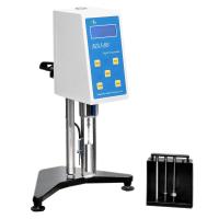
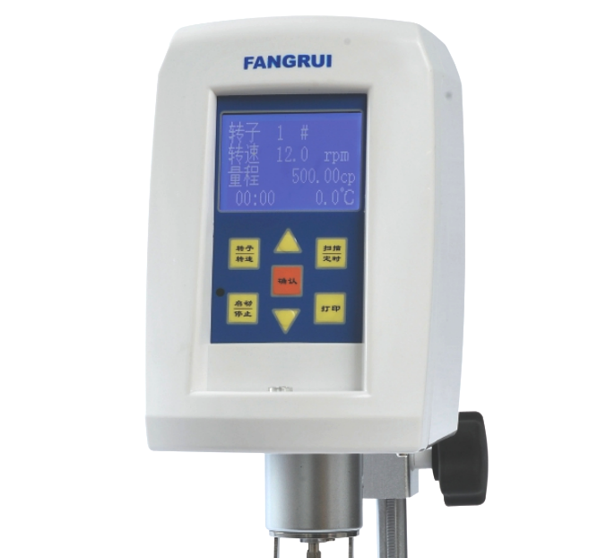
⑴. There are seven buttons and one LED indicator in the panel operation area on the front of the host (Figure 10 Front of the host)
(rotor/speed) key: select the rotor and speed;
(Start/Stop) key: control the operation and stop of the instrument;
(△ and ▽) keys: adjust the corresponding parameters;
(Confirm) key: Confirm parameter values and some options;
(Scanning/Timing): Enable auto-scanning function and timing auto-stop function;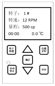
(Print) key: Print the measured data (need to connect a dedicated external printer);
LED indicator light: The indicator light will be on when the motor is running, and the indicator light will be off when the motor is stopped. When the speed is low, the indicator light can be used to judge the operating status of the instrument
⑵. Interface and socket description on the back of the host (Figure 10 Back of the host)
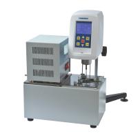
Temperature probe socket: connect the temperature sensor (this piece is an optional accessory);
Power adapter socket: connect the random configured power adapter;
Power switch: the power control switch of the host;
Data output interface: connected to the computer through the data line;
Printer output interface: connect to a portable printer;
⑶. LCD display content description
After starting up, the instrument first displays the model information of the instrument, waits for 3 seconds and then enters the state to be tested. At this time, there are four lines of content in the LCD screen: (picture right)
Rotor: the rotor number in the current state;
Speed: the speed in the current state;
Range: the full scale value of the corresponding rotor and speed;
00.00: Pre-set time value for timing test stop, the longest can be set to 60 minutes, the shortest can be set to 30 seconds, the default time is not set when power on.
0.0°C: The current temperature value measured by the temperature probe (if the temperature probe is not inserted, it will be displayed as 0.0°C)
This machine has a power-off memory function, that is, the set rotor, speed, and timing time will continue to be retained in the restart display interface after power-off and restart , so as to facilitate the user's operation and use.
operation method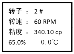

Press the "Rotor/Speed" key, after selecting the appropriate rotor and speed, press the " Start " key to start the test. The test screen display is shown in Figure 12. When the viscosity data of the tested sample is displayed on the screen, do not rush To read the viscosity value, you should let the instrument rotate 4 to 6 times and first observe the "%" value on the bottom line. This value is only valid if it is between 10% and 95%, and you can read the viscosity value at this time . If the "%" value is less than 10% or greater than 95%, it is considered that the current range selection is not suitable, and other ranges should be switched. (The specific operation method is: if the "%" value is less than 10%, the range selection is too large, and the range needs to be reduced, and the speed can be increased or the large-volume rotor can be replaced; if the "%" value is greater than 95%, the range selection is too small, and the volume needs to be increased. range, you can reduce the speed or replace the small-volume rotor).
The instrument has a full-scale overflow alarm function. When the torque value is greater than 95%, the viscosity value will be displayed as "EEEEEE" and accompanied by a buzzer alarm. At this time, it should be switched to a larger range for testing.
For viscosity measurement of unknown samples, the viscosity value of the sample should be estimated first. Then select the corresponding groups of rotors and rotational speed combinations for measurement. When the approximate viscosity value of the tested fluid cannot be estimated, it should be assumed that the viscosity value of the sample is relatively high, and the test should be carried out with the rotor from small to large (volume) and the speed from slow to fast.
The principle of viscosity measurement is: for high viscosity fluid, choose small (volume) rotor and slow speed;
Low-viscosity fluids use large (volume) rotors and fast speeds;
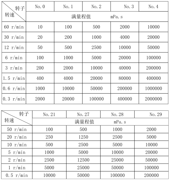
Please refer to the following table for the test range corresponding to the combination of each type of rotor and speed: