(1) Take out all the parts of the machine from the packing box, and install .
(2) Place the heating furnace under the main body of the viscometer, adjust the leveling feet of the heating furnace base so that the water bubbles in the horizontal bubbles of the heating furnace base are in the center, and tighten the fastening nuts of the leveling feet after the adjustment is completed.
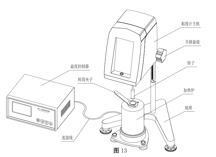
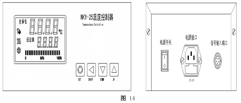
(3) Insert the lead wires of the heating furnace into the signal input ports on the back cover of the temperature controller. See Figure 13 for the appearance after installation. (Please pay attention to the direction when inserting the lead wire . Only when the protruding groove corresponds to the corresponding position can it be inserted and connected.) For the front and back views of the NKY-25 temperature controller, see Figure 14 for details
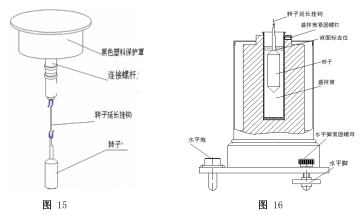
(4) Remove the plastic protective cap of the rotating shaft under the main body of the viscometer, screw the rotor extension hook clockwise (reverse thread) into the universal joint , and select the rotor to be used according to the viscosity range of the sample. See Figure 15 for details
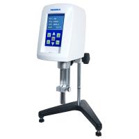
(5) According to the selected rotor, take the corresponding measured sample amount (see Table 1 for details) and put it into the barrel (it can be converted into mass according to the density of the sample) to avoid sample overflow or insufficient amount. When the sample is initially used, the state of the sample is fluid enough to insert the rotor into the sample. At this time, please insert the selected rotor into the sample together. If the sample is solid or paste-like when first used , the rotor cannot be inserted into it. Insert the rotor when the temperature rises and the sample begins to melt . If conditions permit, put the rotor in an oven to keep the temperature near the set temperature, and when the sample temperature reaches, hang the rotor on the extension hook with needle-nose pliers and insert it into the sample for testing.
(6) After the rotor is placed in the sample, check whether its liquid level mark (see Figure 16 for details) is appropriate, and the rotor can be adjusted to a suitable height by lifting the knob.
(7) When the test is completed, use a special handle to take the sample cylinder out of the inner hole of the heating furnace. Please be careful not to burn yourself.