The measurement of coating thickness is a problem for both finishers and companies receiving finished components. Poor coatings can cause rust. Product liability therefore requires quality control of coatings and, in many cases, recording of measurement results in electronic format. Conflicts can arise if the manufacturer and customer of a finished product use different methods or types of instruments to determine coating thickness. This article will discuss the test methods that can be used to determine coating thickness, common applications, and coating thickness instruments.
Test Methods
The magnetic induction method measures non-magnetic coatings on ferrous substrates and magnetic coatings on non-magnetic substrates. The process is straightforward as the probe is placed on the part to be measured. After the probe is placed, the linear distance between the probe tip in contact with the surface and the underlying substrate is measured.
Inside the measuring probe is a coil that generates a changing magnetic field. The magnetic flux density of this field changes when the probe is placed on the substrate. The change in magnetic induction is measured by the secondary coil. The output of the secondary coil is transmitted to a microprocessor where it is viewed as a measurement of coating thickness on a digital display.
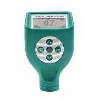
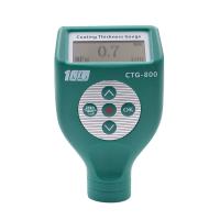
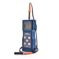
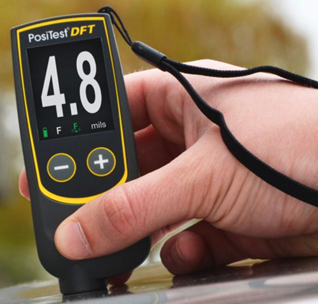
The magnetic induction method is fast and can be used with benchtop or handheld coating Thickness Gauges. It is also non-destructive, relatively low cost, easy to operate, accurate and repeatable, and measurements can be taken instantly through the digital display.
Common applications of this test method include liquid or powder coatings, and plating of chromium, zinc, cadmium, or phosphate coatings on steel or iron substrates.
The eddy current method of coating thickness measures non-conductive coatings on non-ferrous conductive substrates, non-ferrous conductive coatings on non-ferrous metal substrates, and certain non-ferrous coatings on non-ferrous metals. It is very similar to the magnetic induction method and even uses many of the same probe designs. The advantages of eddy current methods are also very similar to those of magnetic induction, including low cost, ease of operation, accuracy and repeatability, and instantaneous measurement with a digital display.
The probe used for eddy current coating thickness measurement also contains a coil. This probe/coil is driven by a high frequency oscillator to generate an alternating high frequency field. When this field is close to a metallic conductor, eddy currents are induced in this conductive material, which causes a change in the impedance of the search coil.
The distance between the probe coil and the conductive substrate material determines the amount of impedance change. Thus, coating thickness is determined by the change in impedance in the form of a digital readout.
Common applications for eddy current coating thickness measurement include liquid or powder coatings on aluminum and non-magnetic stainless steel, and anodizing on aluminum.
Choose a Thickness Gauge
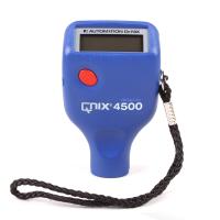
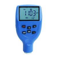
Many Thickness Gauges available today combine magnetic induction and eddy current methods. This allows users to perform multiple measurement tasks without having to switch gauges. Users can also choose between basic gauges that simply provide numerical values on a digital display, or gauges that store measurements and provide statistical information such as average, standard deviation, and high/low values.
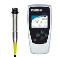
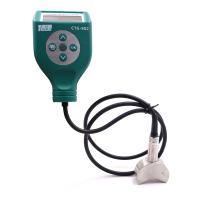
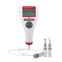
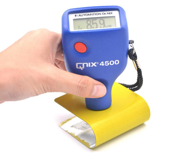
Another important selection criterion is based on the shape of the part to be measured. Not all parts can be measured using a gauge with a built-in probe. Units that provide probes on the cable provide greater flexibility in multi-part configurations. Many units with individual probes also offer the ability to swap probes if the application changes. For example, measuring coating thickness on the inside diameter of a pipe may require a 90-degree probe, while measurements on flat surfaces are better off using a zero-degree probe. Factors such as curvature, edge effects, surface roughness, substrate thickness, magnetic permeability and electrical conductivity all affect the measurement of coating thickness, but can be accounted for with proper calibration.
As mentioned earlier, the ability to store metrics for later documentation and report generation is often very important. For example, these types of reports can help determine jetting patterns and can also be used for incoming inspection of parts. Some manometers have on-board radio transmitters that allow the user to send readings in real time to a computer up to 60 feet from where the measurement is being taken. Data can be entered directly into statistical process control programs without keying in data saving time and eliminating entry errors.
Another option for coating thickness measurement and data logging is a benchtop system. The benchtop system offers a large digital display for comprehensive statistical evaluation of measurements. This includes mean, standard deviation, coefficient of variation, maximum and minimum values, number of measurements, statistics for individual readings or groups; calculation of process capability factors; probability plots for histogram tests for normal distribution; automatic grouping after N measurements and / or automatic final evaluation after N groups; and group evaluation based on group number or group ID. Some desktop systems even offer customer-specific print form templates.
In addition to the documentation benefits, some benchtop systems can combine multiple test methods into one measurement system. A single unit that combines multiple testing methods can benefit companies that may be plating and painting parts in another division. Such systems also use separate probes, which means they have a wider range of applications than built-in coating Thickness Gauges.
special application
并非所有的涂层厚度应用都像在钢上测量油漆一样简单。由涂在镀锌钢板上的涂料组成的涂层有时称为双相涂层,在汽车工业中经常使用。油漆和镀锌的各个层的厚度都很重要。在汽车车身制造中,锌的厚度在零到10μm之间。油漆厚度通常最大为150μm。
镀锌涂层由钣金供应商通过热浸镀锌或电镀锌来施加。如果锌涂层的厚度均匀,则可以使用常规的磁感应涂层厚度测量仪测量随后施加的油漆涂层的厚度。只需从实际读数中减去一个常数即可。
然而,当形成片材时,锌的厚度改变。在成型过程中,严重弯曲的区域可能会发生锌涂层的流动甚至刮落。厚度可能会在3到9μm之间变化,有时会完全去除涂层。
修复因打磨和随后重新喷涂缺陷区域而导致涂层缺陷的车身区域时,可能会遇到类似情况。在这种情况下,如果使用常规的涂层厚度测量系统,也可能会打磨掉锌涂层,从而导致涂料厚度明显减少。这不仅对于检查是有问题的,而且对于电泳漆的质量也重要性无庸赘述,因为该厚度通常仅为约20μm。通过减少的锌涂层在厚度测量中产生的5-6μm的误差将超过公差极限。
为了减轻车辆的重量,一些汽车制造商在与安全性无关的车身部件中使用了越来越多的铝板。可以使用常规的涡流通道来测量铝合金基材上的涂层厚度,以According to标准测量涂料的厚度。在没有人工干预的情况下(操作员甚至可能都不知道零件是由钢还是铝制成的),仪器在探头触碰后立即自动选择双相或涡流方法,并以一种简单的方式存储油漆厚度数据不论钣金类型如何,都可以评估涂料分布。
其他厚度测量技术
还有其他测量涂层厚度的方法,特别是在汽车应用中。这些包括库仑法,β反向散射和X射线荧光技术。
库仑法具有许多重要功能,例如在汽车应用中测量双相镍涂层。该技术涉及通过涂层的局部阳极剥离来确定金属涂层区域的重量,基于每单位面积的质量计算厚度。
使用电解池进行厚度测量,该电解池装有专门选择用于剥离特定涂层的电解质。恒定电流流过测试池,以镀覆用作阳极的涂料。在电流密度和表面积恒定的情况下,涂层厚度与剥离涂层所需的时间成正比。
该方法对于测量导电基底上的导电涂层特别有用。
Beta backscattering begins when a test sample is exposed to beta particles that emit the beta isotope. A beam of beta particles is directed onto the coated component through a small hole through which a fraction of these particles are backscattered from the coating to penetrate the very thin window of a Geiger-Müller (GM) tube. The gas in the GM tube is ionized, creating a momentary discharge across the tube electrodes. The discharge in the form of pulses is counted by an electronic counter and converted into a coating thickness.
Materials with relatively low atomic numbers exhibit significantly lower scattering rates than materials with high atomic numbers. For example, for an assembly with copper as the substrate and a gold coating (thickness 40 inches), beta particles are scattered by the substrate and coating materials. If the coating thickness increases, the backscatter rate increases. Therefore, the change in the rate of particle dispersion is a measure of the thickness of the coating.
This technique works when the atomic numbers of the coating and the substrate differ by 20%. Applications include thickness measurement of gold, silver and tin on electronic components, coatings on cutting tools, decorative coatings on sanitary fixtures and vapor deposited coatings on electronic components, ceramics and glass. Other applications may include organic coatings such as oil or lubricant coatings on metals.
X-ray fluorescence (XRF) is a versatile, non-contact coating thickness measurement method for very thin multilayer alloy coatings on small parts.
Measurements are made by exposing the part to X-rays. A collimator focuses the X-rays onto a precisely defined area of the specimen. This X-ray causes a characteristic X-ray emission (fluorescence) of the coating and base material. The emission is detected with an energy dispersive Detector.