1. Product use and overview
This product is a salt spray corrosion test device for artificially simulating marine climate and environmental conditions. It can conduct salt spray corrosion tests on paint or paint coatings, product coatings, electrical equipment, electronic components, and metal materials.
The device can be used according to the national standard GB2423.17 "Basic Environmental Test Procedures for Electrical and Electronic Products Test ka: Salt Spray Test Method" and IEC68-2-11 "Basic Environmental Test Procedures Part II: Test, Test ka: Salt Spray " and ISO9227 "Artificial Simulated Weather Corrosion Test - Salt Spray Test" and other standards for relevant salt spray tests.
The design and production of this product implement the national standard GB10587 "Technical Conditions for Salt Spray Test Chamber". This device should not be used as an unconventional project test unless it has undergone careful professional demonstration and strict safety test.
2. Environmental conditions for product use
1. Temperature: 15℃~35℃;
2. Relative humidity: not more than 85%;
3. Atmospheric pressure: 86kPa~106kPa;
4. There is no strong vibration in the work site;
5. No sunlight or other direct radiation from cold and heat sources;
6. There is no strong air flow around;
7. There is no strong electromagnetic field around;
8. There is no high concentration of dust and corrosive substances in the working space;
9. Power supply conditions AC: 220±22V, 50±0.5Hz.
3. Main technical indicators
Temperature adjustment range | Room temperature~50℃ | |
temperature fluctuation | ≤±0.5℃ | |
temperature uniformity | ≤2℃ | |
temperature deviation | ≤±2℃ | |
Salt mist deposition rate | 1~2ml / 80cm2.h | |
studio volume | 0.1m3 | |
studio | deep | 500 |
Width | 500 | |
high | 400 | |
Dimensions | deep | 720 |
Width | 1010 | |
high | 1080 | |
total power | 1.2kw (not including compressor) | |
Gross handling weight | 175kg | |
4. Structure and electrical control principle
1. Structure:
The salt spray Test Chamber (see the schematic diagram of the product structure) is mainly composed of a chamber, an air control system, a salt water supply system, a spray device and an electric control system. Its salt mist is generated by air spray. And the range of salt spray spray is adjusted by the spray tower rotary sleeve, so as to form a salt spray test environment in the studio that simulates nature and the experimental medium is evenly distributed.
The working room of the test box is equipped with test rods of different diameters and test slots with angles, which can place test pieces of different shapes. This test box has continuous spray and timing working mode.
2. Electrical control principle:
Press the power switch key to turn on the power, start the Air Compressor through the contactor, and turn on the main circuit. The temperature controller obtains the temperature of the working chamber through the sensor, which is compared with the set temperature value. If the measured temperature is higher than the set temperature, the temperature control instrument will not output a heating signal, and the heating wire will not heat; if the measured temperature is lower than the set temperature, the temperature control instrument will send a heating signal, and the heating wire will be heated to make the work The chamber temperature increases towards the set temperature. So repeated, the temperature of the studio is stabilized at the set value and enters a constant temperature state.
The temperature control principle of the saturator is the same as above.
The timing switch is used to set the timing working state. After pressing this switch, the product works in the time period set by the timer. When the test is over, the product automatically cuts off the power supply to achieve the purpose of safely and reliably controlling the test process. If the timer is not enabled, it will still have to be turned off manually after the test is completed.
This device has double alarm protection function.
If the temperature control instrument is out of control due to some reasons and the temperature exceeds the alarm temperature, the overheating alarm indicator light of the device will be on, the buzzer will sound, and the heating circuit of the Test Chamber and the saturator will be cut off at the same time. It must be shut down for maintenance before it can be restarted. If the alarm function of the instrument fails, the overheat regulator will work and automatically cut off the working power of the heating circuit of the Test Chamber to protect the equipment from damage. The superheat regulator should be adjusted between 60 and 70.
5. Preparation before starting up
1. Place the equipment according to the requirements of the environmental conditions of the product, and configure a fixed gas source and power supply. Open the random parts, place the random parts according to the instructions in the installation manual, connect the water inlet pipe and air inlet pipe, and open the respective shut-off valves. In general, the spray tower can be installed on the left side of the inner wall of the working room, and the salt mist collection device can be installed on the right side of the inner wall of the box to receive the spray.
2. Install the nozzle. Note that the nozzle opening is facing upwards, and the nozzle opening should be in the center of the mixing chamber of the spray tower.
3. Inject distilled water (GB6682) into the air saturator, and the water level should reach the upper mark of the water level tube.
Water injection method: Connect the water outlet below the air saturator to the water outlet of the clean water cylinder with a hose, then fill the water cylinder with distilled water and place it at a high place, turn on the switch to let the water naturally inject into the air saturator. (See Figure 8 in the installation manual)
4. Pour the saline solution prepared according to the regulations into the brine tank.
5. Connect the Air Compressor air pipe to the air source inlet and clamp it with a clamp to prevent the air pipe from falling off.
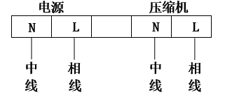
6. Connect the power supply, connect the power supply on the machine and the power supply of the Air Compressor respectively. Wiring method: There is a terminal strip on the back of the box. As shown in the figure below, connect the phase line and neutral line of the single-phase power supply to the "power supply" terminal respectively. Connect the power cord of the Air Compressor to the "compressor" terminal.
7、 在密封水槽内注入清水,注水量以水面和箱盖接触为宜。同时在工作室箱底部注入适量的清水,使工作室底部积水,积水深度达5mm为佳。
8、 一切准备就绪,最后关上箱顶盖,即可开机操作。
六、开机与操作步骤:
操作程序如下:
1、 按电源开(ON)键,接通电源。
2、 用饱和器温控仪表设定饱和器的工作温度,(设定方法参阅随机的温控仪说明书)。
3、 用试验室温控仪表设定试验室内的工作温度。(设定方法同“2”)。
4、 设定压缩机输出压力范围。将随表备用的调整片插入电接点压力表中央槽中,拨动指针,使下限设定在0.2MPa,上限设定在0.4MPa。
5、 拉出减压阀2调整柄并逆时针转至极限位置。
6、 启动压缩机,同时观察电接点压力表的指针,在正常情况下,随着压力增大,压力表指针由零位顺时针转动,当它与上限指针接触时压缩机停止工作,当气压下降,指针逆转与下限指针接触时,压缩机再度启动。
7、 松开过滤减压阀1的锁紧螺钉,转动调整柄(顺时针转压力增大,反之减小),直至阀上压力表示值为0.2MPa,然后锁紧松开的螺钉。
8、 调整喷雾压力:顺时针缓慢转动减压阀2的调整柄并观察喷雾压力表的指针,当压力升至0.1MPa时推入调整柄以锁定喷雾压力,此时可听到试验箱内的喷雾声。
9、 将以上各档压力调整完毕即暂时关闭压缩机。
10、 将过热调节器旋纽转向60~70。
11、 定时功能:定时器最大延时时间为999.9小时,如连续试验时间不超过41天均可采用定时功能。在定时器上设定好所需时间后,只要按下定时键,试验便在时控状态下进行,至试验结束,定时器会自动切断电源。定时器延时时间的设定方法参见本说明书附页。
12、 当工作室试验温度和饱和器温度均达到设定温度并恒定时,可打开箱盖、放入试样,然后合上箱盖,按压缩机键,进入正式试验阶段。
备注:产品出厂时各温控仪和气压表已经过调整,它们的正常工作参数如下:
试验室温控仪参数
试验室 主控设定 SO | 上限报警 SH | 比例带 P | 积分时间 I | 微分时间 d | 输出开关周期 T |
35℃ | 40℃ | 10 | 130s | 30s | 10 |
饱和器温控仪参数
饱和器 主控设定 SO | 上限报警 SH | 比例带 P | 积分时间 I | 微分时间 d | 输出开关周期 T |
40℃ | 45℃ | 5 | 130s | 30s | 10 |
气压表
电接点压力表 | 过滤减压阀1 | 喷雾压力表 | |
下限 | 上限 | ||
0.2MPa | 0.4MPa | 0.2MPa | 0.1MPa |
产品的饱和器和工作室各自配置了独立的加热和温控装置,从接通电源加热到恒温,前者约需30分钟,而后者则需1~2小时。按上述第12条要求,当设备达到恒温后开箱放入试验样品,会由于工作室大量散热导致温度迅速下降,合箱后须经1小时左右才能恢复到设定的恒温。为节省时间,可在完成步骤11之后,先放试验样品,合箱后待二系统均达到恒温时再按压缩机键进入正式试验。期间应注意观察温控仪数据和压力表示值,若有异常应按操作步骤和说明书检查和再行调整。在加热过程中,温度若以设定点为中心,上下波动数回,然后逐步稳定在设定点,应属正常现象。
七、注意事项:
1、 开机后箱体预热过程中常有温度过冲现象,所以初次设定时应略低于工作温度,待温度过冲回落时再设定至工作温度。
2、 试验正式开始后至达到规定时间前应尽量避免开启箱盖,以免热量散失,延长试验过程。
3、 盐雾收集装置是供用户在试验时观察箱内喷雾状况用的,不是计量沉降量大小的器具。用户在试验时应经常观察滴定管上方的玻璃管内是否有水珠滴下,如有水珠滴下表示箱内工作正常,如长时间(一般为4小时左右)无水珠滴下则表示箱内喷雾系统有问题或收集器位置离开喷雾范围,需排除故障后才可开机。
4、 出现不能喷雾现象一般由以下几种情况造成:
(1) 供气压力不够;
(2) 引水管龟裂漏气或水位过低引水管不能浸入水中引水;
(3) 喷嘴中有异物。
排除故障方法:
(a) 调整供气压力;
(b) 检查引水管和调整储液筒内的水位;
(c) 清除喷嘴异物或更新喷嘴。
5、 使用时应注意空气饱和器内水位情况,水位不得低于下标线,以防水位过低而烧毁饱和器内的加热元件。
6、 饱和器在使用一段时间后,应及时更换蒸馏水。
7. A water outlet under the exhaust pipe is used to discharge the condensed saline solution in the diversion pipe. Before work, it should be covered with a catheter and introduced into the waste liquid discharge container.
8. The rubber tubes connecting various parts should be checked frequently for aging and cracking. If there is any aging phenomenon, it should be replaced in time.
9. After the test, the power supply and the air and water inlet shut-off valves should be turned off in time. At this time, there is still mist spraying out of the box, which is the residual gas released by the saturator after each test.
10. After each test, the brine solution in the brine pipeline should be removed in time, and the pipeline should be cleaned with clean water to avoid the formation of crystals in the residual salt solution pipeline, which will cause the nozzle to be blocked when it is used again in the future.
11. After the test is over, the separated matter accumulated in the oil-water separator of the filter pressure reducing valve 1 should be drained.
12. Compressor model: Z-0.08/7 type, single-phase 220V, 50 Hz (this model is for reference and selection by users).