scope of application
When the coating film is bent on the shaft, it is not simply the elasticity of the coating film, but some comprehensive properties, such as tensile strength, tensile strength, adhesion of the coating film to the substrate and elongation of the coating film surface etc., so it is generally called flexibility test.
The YZQ-II coating film cylindrical bending Tester designed and manufactured according to the national standard GB6742-86 and international standards ISO1519 and ASTM-D522 is suitable for the coating of paints and varnishes (including single-layer and multi-layer coatings) with the thickness of the sample plate below 1.0mm. Layer system) under standard conditions, the performance of anti-dry cracking or peeling from the metal sample plate when bending around the cylindrical axis has great reference value for the selection and application of coating varieties.
working principle
The ductility of the coating film to the substrate is different with different bending radii. The flexibility of the coating film can be judged according to the cracking or peeling of the coating film at different bending radii or from the substrate.
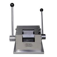
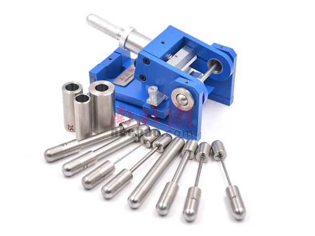
Instrument structure
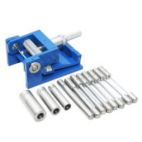
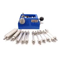
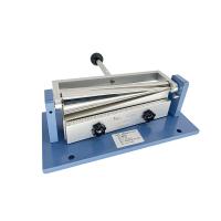
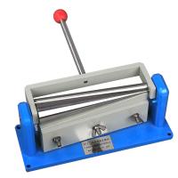
The main structure of the instrument consists of two parts: 1. Machine base, 2. Test rod. The machine base is composed of the clamping and tightening parts of the sample plate and the rotating and adjusting bending mechanism.
Main Specifications
1. The adjustment amount of the rotating and adjusting bending mechanism is ≥17mm, and the gap between the test shaft and the attachment is ≤0.05mm
2. The gap between the clamping and tightening parts of the sample plate and the test shaft is ≤0.1mm
3. Diameter of test shaft: 2, 3, 4, 5, 6, 8, 10, 12, 16, 20, 25 and 32
Among them: 20, 25 and 32mm are shaft sleeves.
Operation method
1. Place the bending Tester on the edge of the test bench, so that the adjusting bending mechanism can hang vertically, and the sample plate (the coated film of the sample plate faces outward, for the test shaft) can be freely inserted into the adjusting bending mechanism between the specimen clamps.
2. According to product requirements, select a suitable test shaft and insert it into the hole of the bending test bench bracket.
3. Rotate the fastening screw on the sample splint. At this time, the sample plate clamped on the sample splint springs up; insert the sample plate from between the adjusting bending mechanism and the test shaft (the coating surface of the sample plate faces outward, for the test axis). Press the sample plate with the horizontal bar on the sample holding plate, and screw the nut on the horizontal bar to fasten the sample plate. It is advisable that the insertion depth of the sample plate should not exceed the horizontal bar. Then rotate the supporting screw on the sample holding plate to make the sample holding plate rise and attach to the test shaft. At this time, the sample plate is also attached to the test shaft.
4. Rotate and adjust the handle of the bending mechanism. At this time, the horizontal top seat on the bending mechanism is slowly advanced until the upper horizontal top seat rests on the sample plate.
5. Hold the handle of the bending mechanism, and within 1S-2S, rotate 180 smoothly and slowly instead of suddenly. . (This is done to avoid heating up the sample plate). At this time, the sample plate on the test shaft is also rotated 180°. .
6. After bending, immediately observe the cracking and peeling of the sample plate (excluding the 10mm coating on both sides of the sample plate).
7. When observing, use normal vision according to product standards, or use a 10-fold magnifying glass. If the coating is observed with a 10x magnifying glass, it must be noted that the 10x magnifying glass is used for observation, so as to avoid misunderstanding with the results of normal vision observation.
8. Adjust the support screw on the sample splint to separate it from the test shaft; adjust the handle of the bending mechanism to separate the horizontal top seat on the bending mechanism from the test shaft; rotate the nut on the horizontal bar on the sample splint to make it The sample plate is no longer compressed. After the above three steps are completed, the sample plate can be taken out. It should be noted that the adjustment bending mechanism needs to return to the original drooping position for the next test.
9. The operating procedure for identifying the diameter of the shaft that first causes damage
According to the above operation steps, test in turn (from large to small) until the coating film cracks or peels off from the substrate. On a new sample plate, repeat the operation with the same shaft diameter. After the results are verified, record the shaft diameter at which the coating film was first cracked or peeled off from the substrate. If the coating film cannot be damaged even at the smallest shaft diameter, it is recorded that the coating film does not break when it is bent on the smallest shaft diameter.
10. Test environmental conditions
In order to make the test result judge correctly, the test should be carried out under the condition of temperature 23±2℃ and relative humidity 50±5%.
11. Specimen specifications Long strip aluminum plate with thickness ≤ 1mm Width 35mm
Thickness ≤ 0.3mm long strip steel plate width 35mm
Precautions for use
1. In order to prevent the coating from being damaged during the bending operation, a thin paper can be attached to the coating film surface of the sample plate during the test, and then inserted into the bender for testing.
2. If a 10x magnifying glass is used to observe the test results, the test results should indicate the use of a 10x magnifying glass.
3. Use the smallest mandrel test that does not cause the film to crack or peel off from the substrate, in which case the diameter of this mandrel should also be indicated.
4. If the aluminum plate is used as the substrate of the sample plate, its long side should be parallel to the rolling direction.
Appendix Calculation of surface elongation of coating film
Assuming that the substrate is in an elastic state (which, of course, it is not, but it is possible given a constraint), the theoretical elongation of the axis of the cylinder can be calculated for each diameter of the cylinder. Under this assumption, the modulus of elasticity in tension and compression are both numerically equal. And in the neutral plane (that is, the plane of neither elongation nor compression of the bent metal plate) is on the centroid axis of the test plate. In a long test plate with thickness t (the thickness of the substrate plus the thickness of the coating film) bent around a cylindrical axis of radius r, the position of the neutral plane should be at a distance of t/2 from the surface of the metal plate , and assuming that the sample plate is bent by 180°, the perimeter of the curved section along the neutral axis is equal to: π(r+t).
From this, the surface elongation and elongation of the coating film can be calculated:
Elongation=π(r+t)-π(r+t/2)=π(t/2)
Elongation %=[(πt/2π(r+t/2)]×100%=[t/(2r+t)]×100%