This method is mainly applicable to coated paper and cardboard, and can also be used for uncoated paper and cardboard or paper and cardboard printing samples with low printing gloss. The difference in sample color and diffuse reflectance has little influence on the determination of gloss. , such as black and white surfaces with the same glossiness, the measurement result of the white surface is less than one gloss unit higher than that of the black surface.
1 definition
(1) Gloss
The nature of directional selective reflection on the surface of an object determines the degree of strong reflected light or object mirroring that can be seen on the surface of the object.
(2) Specular gloss
The ratio of the light flux reflected by the surface of the sample into the specified aperture in the direction of specular reflection (regular reflection) and the reflected luminous flux of the standard mirror under the same conditions, expressed as a percentage.
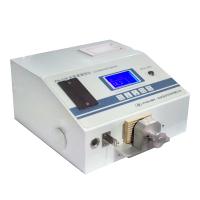
2 instruments
2.1 Optical system of the instrument
The optical system diagram of the 75° angle gloss test head is shown in Figure 8-13.
Its optical system is composed of light source, lens, sample pressing plate and photoelectric device. The overall layout and relative dimensions of the main equipment are shown in Figure 8-13. The dotted line indicates the path of the paraxial ray along the optical axis. Light starts from the light source and passes through the center of the condenser and the shaped field grating. The field grid is used to limit the effective centroid of the filament to fill the filament image. The light continues through the center of the illumination objective and rectangular aperture grating to the specimen. The intersection of the paraxial ray and the sample plane is called the center of the test surface (not necessarily coincident with the geometric center of the test hole). When a front-reflecting flat mirror is placed at the sample position, the paraxial light is reflected by the flat mirror and passes through the center of the receiving hole and the illumination objective lens to image the light source field grid on the receiving hole. The distance "d" from the center of the test surface to the receiving hole As the basis for determining other dimensions, d is not less than 10 cm, and the key dimensions are the angle of incident light and the position and diameter of the receiving hole.
On the photoelectric device that images the surface of the sample by the positive lens close to the receiving hole, in order to receive the light that enters the receiving hole through different paths evenly, a piece of frosted glass can be installed in front of the photoelectric device to make the sample image on the frosted glass. The device receives ground glass scattered light. Double click on the inner wall of the lens barrel of the lens and the photoelectric device. There are extinction gears. In addition to the light reflected by the sample, the stray light entering the receiving hole is absorbed and eliminated by the inner wall.
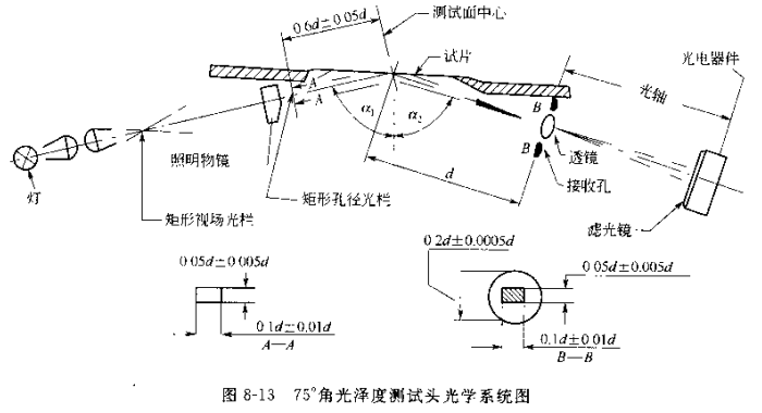
(1) Incident angle The incident angle of the beam axis to the sample is 75°±0.1°.
(2) The diameter of the receiving hole and the receiving hole is 0.2000d±0.0005d, and the edge thickness is less than 0.005d. When the sample is a flat mirror reflected by the front, the paraxial light should pass through the center of the receiving hole vertically after being reflected by the mirror, with a tolerance of 0.004d.
(3) The position and size of the light source field grid - the light source field grid is imaged on the plane of the receiving hole, (along the direction of the optical axis) the position error is allowed within 0.04d. The size of the rectangular image is (0.1±0.01)d ×( 0.05±0.005) d The short side is parallel to the plane of the shot.
(4) Uniformity of light in the field shed The luminous flux in the field grid should be evenly distributed.
(5) The position and size of the aperture grating. The rectangular aperture is perpendicular to the beam axis, (0.6±0.05)d away from the center of the test surface, the size of the grating is (0.1±0.01)d×(0.05±0.005)d, and the short side is parallel to plane of incidence. The incident beam is not limited by other gratings.
(6) The uniformity of light in the aperture grating is the same as that of the light source field grating.
(7) Spectral conditions ﹑ For incandescent lamps with a color temperature of (2850±100)K, use filters to correct the spectral characteristics of optoelectronic devices. The spectral response of the combination of the two should conform to the CIE spectral light efficiency function.
(8) Photoelectric device The photoelectric device and display circuit convert the received luminous flux into digital display, and the conversion accuracy in the whole range should be within 0.2% of the full range, that is, within 0.2 gloss units.
(9) Sample pressing plate﹑testing the pressing plate to tighten the paper sample on the test hole. When necessary, you can turn on the suction switch to form a negative pressure between the pressing plate and the cardboard, and absorb the paper sample on the pressing plate to keep it flat. When the paper sample is a piece of soft plastic film with uniform thickness (such as optical-grade polyester film with a thickness of 0.08 mm), turn on the suction switch, and you can see the image of the filament on the receiving hole. Compare with the filament image produced by the previously mentioned black glass standard. There should be no difference in the position and size of the two.
2.2 Gloss standard
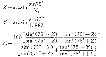
Theoretically, the standard of specular gloss is a perfectly reflective flat mirror, and its gloss value is set at 384.4 gloss units. According to this calculation, the smooth surface with a refractive index of 1.567 is given a gloss value of 100 gloss units by the Fresnel (Fesnel) formula.
① Gao Guangyang's working standards. Measure the refractive index Ne (refractive index of the mercury e spectrum line) of a smooth black glass plate, and calculate the optical density value G of the working standard plate according to the following formula.
②Medium glossiness standard. Objects with reflective properties similar to the paper sample to be tested, such as porcelain plates, can be used as medium gloss standard plates. The surface of the porcelain plate needs to be flat and the glossiness needs to be uniform. Each porcelain plate needs to be calibrated against a black glass standard on a compliant instrument. Scale gloss value.
Note: 1. The standard board should be placed in a closed box when not in use, and kept clean to prevent contamination or damage to the surface. Do not place the working surface of the standard board downward to avoid dirt and wear. When holding the standard plate, hold it by the edge of the plate to prevent the oil, sweat and oil on the hands from contaminating the working surface of the standard plate. The standard board can be dipped in hot water and light washing liquid and gently brushed with a soft brush (do not use soapy water), and then rinsed with hot water near 65°C. Rinse the cleaning solution, and finally rinse it with distilled water, and dry it in an oven at about 70°C. Black glass standards can be lightly wiped with lint-free lens tissue or other absorbent material, but medium gloss standards should not be wiped.
2. As a high-gloss standard black glass plate, the surface refractive index will gradually change after several years, so it is recommended to be verified by the superior metrology department every 1 year, and it is better to re-polish the surface to restore its original state.
③Black tube with black velvet lining.
3 Preparation of samples
①According to standard methods, take samples, process samples, and test under standard conditions.
②Avoid watermarks, spots and visible paper defects from the extracted paper, and cut 5 test pieces of 100 mm×100 mm evenly along the transverse paper web, keep them clean, and do not touch the test surface with hands. (Sample gloss tends to decrease irreversibly in a high humidity environment, so be careful not to get the sample wet.)
4 Test steps and result calculation
① Turn on the power according to the instrument manual, and after preheating to the specified time, insert a black glass standard plate at the sample position, and adjust the reading to the calibration value of the standard plate.
② Replace the black tube and adjust the reading to zero.
③ Replace with a black glass standard plate to calibrate again, and then replace with a medium gloss standard plate to read the gloss value, the reading should be close to the calibration value of the standard plate. If the difference exceeds 1 gloss unit, it is necessary to check the geometry, optical harmony and photometer characteristics of the instrument, or recheck the calibration values of the two standard plates.
④ After calibrating the instrument with the standard plate and black tube, insert the sample to read the optical density value. Unless otherwise specified, generally the front and back sides of each sample need to be tested in both vertical and horizontal directions. During the test, the instrument can be calibrated repeatedly with the standard plate and black tube, and then checked again after the test to ensure that the instrument is always calibrated correctly.
⑤ Take the average value of the vertical and horizontal values for each side as the gloss value, and calculate the average value and coefficient of variation of the gloss of the front and back sides of 5 samples respectively, accurate to 1 gloss unit.