1 definition
(1) Stiffness is the force or moment when bending a specimen of specified size clamped at one end to an angle of 15° under standard conditions. Expressed in mN or mN·m.
(2) Bending length is the radial distance between the specimen holder and the stressed position of the specimen sheet.
(3) Bending angle The angle between the initial position of the specimen piece and the position after the force is applied.
2 principle
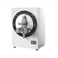
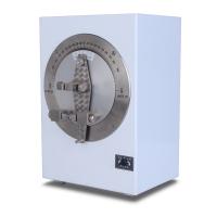
The instrument is designed according to the principle of moment balance on the center of the rotating shaft, and its working principle is shown in Figure 8-24 below.
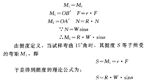
Before the instrument is started, the pendulum and the sample are in a vertical position, and the center line of the pendulum coincides with the center line of the sample and the angle plate, which is equivalent to the OBA position in the figure. When the instrument is running, the pendulum and the angle plate rotate clockwise, and at the same time, the angle plate drives the paper pusher to rotate, so that the paper pusher produces a bending moment on the sample. When the relative included angle between the center line of the pendulum and the center line of the angle plate is 15°, that is, the sample is bent at an angle of 15°, stop running. At this time, the position of the center line of the pendulum is equivalent to OA' in the figure. Try The positions of the sample and the pushing paper ~ are equivalent to (B' in the figure, and a torque balance system is formed with the rotating shaft as the center, that is, the force F acting on the sample by the pushing paper S acting on the pendulum through the sample clamp and the moment Mn on the pendulum The component force N of the weight acts on the moment M on the pendulum. The balance moment formed. Both moment values are equal, namely:
3 instruments
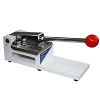
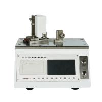
The structure of the instrument is shown in Figure 8-25, which includes a transmission part and a test part.
① Transmission part. It consists of a micro motor and a gear system. Start the motor to drive the angle disc to rotate through the gear system.
② Test part. It is composed of load plate, angle plate, load pendulum, paper pusher, sample holder, etc.
The load plate is a fixed plate, which is driven by a motor through gears. It is marked with 7.5° and 15° scale marks. The lower part of the angle plate is equipped with a paper pushing frame, and a pair of paper pushing sticks are installed on the frame. When measuring, the sample is bent and bent by pushing the paper wheel.
The load pendulum is supported on the main shaft and can swing around the shaft. There is a counterweight on the upper part of the pendulum, and a small shaft on which the weight is placed on the lower part. Install a sample holder at the center of rotation of the pendulum, and the center of its lower edge coincides with the center of rotation.
4 Instrument Calibration
① Adjust the instrument to level, and then adjust the angle plate, so that the center line of the pendulum coincides with the zero line of the angle plate and the load plate.
② Calibration of pendulum sensitivity. Move the pendulum to an angle of 15°, release the pendulum so that it can swing freely, and the number of swings should not be less than 20 times.
5 Experiment preparation
① Carry out sampling according to the standard method.
② Carry out temperature and humidity treatment according to the standard method.
③ Cut the sample into a rectangle with a length of 70 mm and a width of (38±0.2) mm. When measuring longitudinal and transverse stiffness, the direction consistent with the longitudinal direction of the sample piece is the testing direction. Five specimens are required for each direction.
④ Tested under standard temperature and humidity conditions.
6 tests
①Fire one end of the sample into the tip of the sample, and be careful not to clamp the clip too tightly, so as not to cause damage to the sample and deviation of readings.
② When testing with the Taber instrument, pay attention to make the sample coincide with the center line of the pendulum. It is better to use the small roller distance adjustment device to adjust the sum of the distance between the sample and the two small rollers to (0.33 ± 0.03 ) mm,
③According to the different stiffness of the sample, select the measurement range by changing the weight, so that the reading of the sample on the load plate is between 20 and 70 scales.
④Start the instrument to bend the sample, stop the operation immediately when the center line of the pendulum coincides with the 15° line of the angle plate, and read the value indicated by the center line of the pendulum on the load plate, accurate to half a division. The above operations are carried out in the left and right directions respectively. The average value of the scale when the test sample faces the positive and negative sides at 15°. If the sample stiffness is too large or breaks when bent at 15°, it can be changed to stop at 7.5°, read the scale value, and then multiply by 2 to get the approximate value when bent at 15°. In this case, it should be noted in the report.
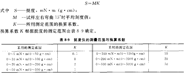
7 Calculation of results
The stiffness of the sample is calculated according to the following formula:
According to the vertical and horizontal 5 for the measurement. The result is expressed as the arithmetic mean of all measured values in the vertical and horizontal directions, and the maximum and minimum values are reported. Calculation results are rounded to three significant figures.